65
INSTRUMENTS AND CONTROLS
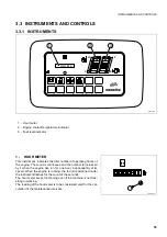
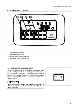
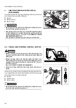
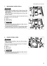
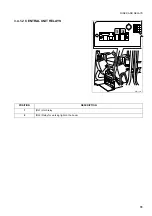
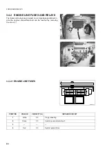
12 - OPTIONAL EQUIPMENT CONTROL SELEC-
TION SWITCH
13 - HYDRAULIC PLIERS USE ENABLING SWITCH
CAUTION
•
This switch must be used only for equipment that requires
continuous and prolonged operation (for example, the
bush cutter).
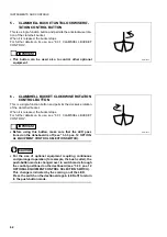
This switch changes the function of the control positioned on the
right joystick lever (see “3.3.3 pos. 6 CLAMSHELL BUCKET
CLOCKWISE ROTATION BUTTON”) from push-button mode into
switch mode.
With the LED off, the control on the right joystick is always in
push-button mode, as required for the standard setting of the ma-
chine.
With the LED on, the control on the right joystick changes over to
the switch mode.
This function is activated by pressing the switch once and discon-
nected by pressing it again.
IMPORTANT
☞
•
If the machine is not fitted with optional equipment the op-
eration of this switch is inhibited.
RYA13830
IMPORTANT
☞
•
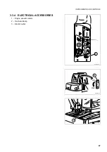
This device enables the operation of the hydraulic pliers
control.
When this switch is pressed, the LED comes on and activates the
hydraulic pliers control circuit.
The hydraulic pliers control is operated through the pedal posi-
tioned near the driver’s seat, on the left side (see “3.3.5 pos. 4
POSITIONER OR HYDRAULIC PLIERS CONTROL PEDAL”).
When the switch is pressed again (LED off), the control is discon-
nected.
RWA18240
Summary of Contents for PC110R-1
Page 2: ......
Page 19: ...17 SAFETY AND ACCIDENT PREVENTION...
Page 51: ...49 THE MACHINE AND ITS OPERATIONS...
Page 126: ...124 PAGE INTENTIONALLY LEFT BLANK...
Page 127: ...125 MAINTENANCE...
Page 190: ...188 PAGE INTENTIONALLY LEFT BLANK...
Page 191: ...189 TECHNICAL SPECIFICATIONS...
Page 198: ...196 PAGE INTENTIONALLY LEFT BLANK...
Page 199: ...197 AUTHORISED OPTIONAL EQUIPMENT...


