background image

PRECAUTIONS TO BE TAKEN WHEN WORKING

36

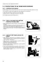
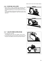
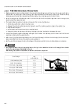
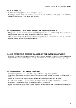
2.4.8 PREVENTING 

ELECTROCUTION 

Digging operations near overhead electric lines are extremely dangerous and they may also cause death due to
electrocution; for this reason, when working near overhead electrical lines always respect the minimum safety
distances prescribed by the competent authorities and by the accident-prevention rules in force.

As far as underground long-distance lines are concerned, the minimum distance depends on the covering of the
ducts in which the cables are laid.

The basic safety precautions to be taken to prevent this risk are the following:

1 – Wear shoes with thick rubber or leather soles.

2 – Request the aid of another person who can warn you if the machine gets too close to the electric line.

3 – Operate at low speed.

4 – Learn what is to be done first in case of electrocution.

5 – Keep the phone number of the electricity company and of the nearest first aid station at hand.

If the work equipment gets accidentally entangled in the cables, the operator must not leave the cab until the
electricity company has insulated the line.

When carrying out this kind of operations, warn everyone standing in the work area to keep at the minimum dis-
tance prescribed from the machine and the work equipment.

Ask the electricity company what are the voltage of the cables and the minimum safety distance in advance.

DANGER 

The minimum distances from overhead lines can vary in the different countries, according to the climate
and to the percentage of humidity in the air.
Indicatively, the distances indicated in the table should be respected.

Cable voltage 

Min. 

safety distance

1.0 kV (distribution line)

5 m

6.6 kV (2–3 insulators)

5.2 m

33 kV (min. 3 insulators)

5.5 m

66 kV (min. 6 insulators)

6 m

154 kV (min. 10 insulators)

8 m

275 kV (min. 19 insulators)

10 m

RYA15390

Summary of Contents for PC110R-1

Page 1: ...afe use of this machine may cause serious injury or death Operators and maintenance personnel must read this manual before operating or maintain ing this machine This manual should be kept inside the...

Page 2: ......

Page 3: ...ions that have been carried out are important to have a clear prospect of the situation and to know exactly what has been done and what has to be done after the next maintenance interval Therefore it...

Page 4: ...indicate the risk of damage to the machine on ly This word is used when precautions are indicated which must be taken to avoid actions that may shorten the life of the machine Komatsu Utility cannot r...

Page 5: ...s property or the machine if this has been tampered with by modifying the standard setting of the hydraulic system DANGER Before carrying out any electrical welding disconnect the battery and the alte...

Page 6: ...the work IMPORTANT The instructions regarding the authorized optional equipment are given in the relevant operation and maintenance manuals if the equipment is supplied by Komatsu Utility these publi...

Page 7: ...operation its potential yield and its function ality will be untimely reduced Every new machine must be used carefully paying special attention to the following indications After the start let the en...

Page 8: ...bers of the components are the only numbers that must be indicated to the Dealer when requiring assistance and ordering spare parts RYA14760 The machine serial number is stamped on the front right par...

Page 9: ...EISTUNG PUISSANCE MOTEUR MASSA MAX ASSE ANT MAX WEIGHT FRONT AXLE ZUL ACHSLAST VORN POIDS MAX ESSIEU AV MASSA MAX ASSE POST MAX WEIGHT REAR AXLE ZUL ACHSLAST HINTEN POIDS MAX ESSIEU AR kg kw kg kg RWA...

Page 10: ...r of the travel reduction gear is stamped on the plate positioned on the outer side of the reduction gear cover The serial number of the swing reduction gear is stamped on the plate positioned on the...

Page 11: ...PRODUCT IDENTIFICATION 9 1 4 7 SERIAL NUMBERS AND DEALER S ADDRESS Machine n Model Engine n Travel reduction gear n Swing reduction gear n Dealer Address Tel Person to contact NOTES Cab n...

Page 12: ...OR IS SUBJECTED 24 2 2 GENERAL PRECAUTIONS 25 2 2 1 GENERAL SAFETY RULES 25 2 2 2 SAFETY DEVICES AND GUARDS 25 2 2 3 CLOTHING AND PERSONAL PROTECTION ITEMS 25 2 2 4 UNAUTHORIZED MODIFICATIONS 26 2 2 5...

Page 13: ...41 2 8 PRECAUTIONS TO BE TAKEN DURING MAINTENANCE 42 2 8 1 WARNING PLATES 42 2 8 2 TOOLS 42 2 8 3 PERSONNEL 42 2 8 4 EQUIPMENT 43 2 8 5 WORKING UNDER THE MACHINE 43 2 8 6 KEEPING THE MACHINE CLEAN 43...

Page 14: ...THE AIR CONDITIONING SYSTEM if provided 82 3 5 GUARDS AND DRIVER S SEAT 84 3 5 1 ENGINE HOOD 84 3 5 2 SIDE COVER 84 3 5 3 CAB 85 3 5 4 VENTILATION AND HEATING 89 3 5 5 AIR CONDITIONER if provided 90...

Page 15: ...G THE WORK EQUIPMENT 112 3 12 1 ORGANIZING THE WORK AREA 112 3 12 2 POSITIONING THE BUCKET ACCORDING TO THE WORK TO BE CARRIED OUT 112 3 12 3 POSITIONING THE MACHINE FOR DIGGING OPERATIONS 113 3 12 4...

Page 16: ...KING CLEANING OR CHANGING THE AIR CLEANER CARTRIDGE 145 4 7 1 b CHECKING AND CLEANING THE CAB AIR FILTER 147 4 7 1 c CHECKING AND CLEANING THE AIR RECIRCULATION FILTER only for machines equipped with...

Page 17: ...TER 172 4 7 11 e CHANGING THE FUEL FILTER 173 4 7 11 f DRAINING THE FUEL TANK 174 4 7 11 g CLEANING THE OUTSIDE OF THE RADIATORS 174 4 7 11 h CLEANING THE OUTSIDE OF THE A C CONDENSER only for machine...

Page 18: ...198 6 1 1 PRECAUTIONS REGARDING SAFETY 198 6 1 2 PRECAUTIONS REGARDING THE INSTALLATION OF EQUIPMENT 199 6 1 3 CHARACTERISTICS OF THE OPTIONAL EQUIPMENT 200 6 2 ARRANGEMENT FOR THE INSTALLATION OF TH...

Page 19: ...17 SAFETY AND ACCIDENT PREVENTION...

Page 20: ...ith a solution made of water and detergent Do not use fuel petrol or solvents If the plates are damaged ask for new ones to Komatsu Utility or to your Komatsu Utility Dealer In case of replacement of...

Page 21: ...tion and maintenance of the machine must know the symbols contained in the pictograms perfectly the following description illustrates what they look like and their respective meanings RWA00020 Do not...

Page 22: ...C SYSTEM WITH OIL HYDRAULIC OIL TOPPING UP REFUELLING ENGINE LUBRICATING OIL FILTER Do not get near or stand within the machine working area RWA18280 RWA34380 BIO OIL Only for machines in which the sy...

Page 23: ...SE AND VIBRATION PLATES 21 FUEL FILTER ENGINE AIR SUCTION FILTER ENGINE COOLANT PRESSURE HYDRAULIC OIL LEVEL HYDRAULIC OIL FILTER ELECTRIC OUTLET D RWA00060 RWA00090 RWA00110 RYA12880 H L RWA00070 12...

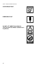
Page 24: ...SAFETY NOISE AND VIBRATION PLATES 22 ANCHORAGE POINT EMERGENCY EXIT DO NOT LIFT MORE THAN 1000 KG Only for machine without overload warn ing device RWA00200 RWA00190 1000 Kg RYA12890...

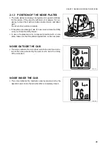
Page 25: ...ents If the plates are damaged ask for new ones to Komatsu Utility or to your Komatsu Utility Dealer In case of replacement of a component provided with a noise plate make sure that this plate is appl...

Page 26: ...JECTED According to the results of the tests carried out to determine the vibrations transmitted to the operator by the ma chine the upper limbs are subjected to vibrations lower than 2 5 m sq sec whi...

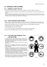
Page 27: ...t see 3 5 6 SAFETY BELT Do not remove the safety devices and always keep them in good operating conditions Improper use of the safety devices may result in serious injuries or even death RWA00960 Do n...

Page 28: ...erator s seat even if temporarily make sure that the machine is in a safe position See 2 4 13 PARKING THE MACHINE Before leaving the operator s seat carry out the following opera tions in the sequence...

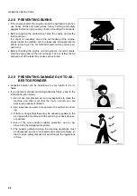
Page 29: ...f it is dirty with oil grease mud or rubble RWA18670 RWA00970 RWA00980 Fuel oil and some types of antifreeze can be easily ignited if they get in contact with a flame Fuel is particularly flammable an...

Page 30: ...ol down The hot oil that can be sprayed out of the tank may cause serious burns RWA01000 RWA01010 Asbestos powder can be hazardous to your health if it is in haled If you handle materials containing a...

Page 31: ...e neces sary disinfectants bandages medicins etc It is necessary to know what to do in case of fire Make sure that you have the phone numbers of the persons or structures you may need to contact in ca...

Page 32: ...in order to find out their exact positions or to make them inneffective until the end of the operations Be careful not to sever or damage any of these lines Check the depth and flow of water before op...

Page 33: ...a Make sure that all the working lights and bulbs are functioning properly If necessary replace faulty bulbs with new ones making sure that the power is correct Remove any trace of dirt from the cab w...

Page 34: ...ioned on the back side of the machine the travel levers must be operated in the opposite direction In this condition be careful not to confuse the travel movements while using the machine See 3 6 5 HO...

Page 35: ...nt control levers must be used during travel avoid moving them abruptly sudden manoeuvres change the attitude of the machine and make driving difficult When travelling on rough ground keep the speed l...

Page 36: ...pes It is advisable to go down or up to a flat place to perform these operations Do not travel on wet grass or thick layers of leaves if the ma chine moves obliquely in these conditions it may slip Do...

Page 37: ...urn It is particularly dangerous to swing on slopes when the bucket is full If these operations must be long accumulate soil in such a way as to create a horizontal platform on which the machine can b...

Page 38: ...be done first in case of electrocution 5 Keep the phone number of the electricity company and of the nearest first aid station at hand If the work equipment gets accidentally entangled in the cables...

Page 39: ...snow and are not visible therefore proceed with care when clearing the snow When working in tunnels galleries under electric cables or other ducts air telephone lines and wherever the height is limit...

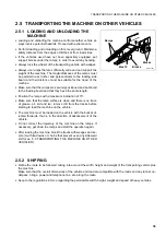
Page 40: ...gine 3 Put wedges or safety blocks under the tracks Always rest the work equipment on the ground if it is necessary to park with raised arms make sure that the safety locks are en gaged Lock the equip...

Page 41: ...anchored to the loading board and that they have the same length Position the ramps with a maximum inclination of 15 Make sure that the ramp surface is clean and there is no trace of grease oil soil a...

Page 42: ...rogen which is highly explosive and can be easily ignited with small sparks or naked flames Before working with batteries stop the engine and remove the ignition key Avoid short circuiting the battery...

Page 43: ...nes or the cable Do not stand astride the cable Move the machine just far enough to permit the required re pairs Put wooden blocks between the towing cable and the machine body in order to avoid wear...

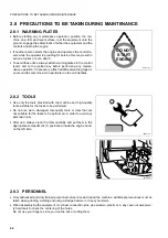
Page 44: ...attach additional warning tags al so around the machine and in particular on the cab handles RWA01310 RWA18700 1 Use only the tools provided with the machine and high quality tools suitable for the ta...

Page 45: ...ttered tools or broken pieces are dan gerous because they may cause someone to slip or trip Al ways keep the machine and the work site clean and tidy To clean the machine use a pressurized jet of warm...

Page 46: ...es Periodically change the following parts which are important to prevent fires Fuel supply system fuel delivery and return pipes Hydraulic system main delivery pipes of the hydraulic pump Even if the...

Page 47: ...up the fuel and oil tanks in properly ventilated areas and refrain from smoking When refuelling hold the fuel gun firmly and keep it constantly in contact with the filler until you have finished in or...

Page 48: ...rst the negative earth cable and then the positive cable At the end of the operation reconnect first the positive ca ble and then the negative cable If electrical welding operations are to be carried...

Page 49: ...re lease the pressures and the residual pressure present in the tank Small leakages from pipes under pressure and the resulting jets are extremely dangerous since they can perforate the skin and penet...

Page 50: ...t is not possible to mix the synthetic biodegradable oil type HEES with ordinary hydraulic oils since when the temperature increases insoluble compounds are generated which are deposited on the filter...

Page 51: ...49 THE MACHINE AND ITS OPERATIONS...

Page 52: ...travel position the upper structure so that it is directed towards the blade before engaging the antirotation lock Non compliance with these rules may cause serious accidents The machine is provided...

Page 53: ...W MONOBOOM 1 Bucket 2 Bucket cylinder 3 Arm 4 Arm cylinder 5 Boom 6 Revolving support 7 Cab 8 Sprocket 9 Undercarriage 10 Track 11 Blade cylinder 12 Idler roller 13 Blade 14 Boom swing cylinder 15 Lif...

Page 54: ...m cylinder 5 Two piece boom upper part 6 Two piece boom cylinder 7 Two piece boom lower part 8 Revolving support 9 Cab 10 Sprocket 11 Undercarriage 12 Track 13 Blade cylinder 14 Idler roller 15 Blade...

Page 55: ...afety lever 2 Arm rotation control 3 Lifting bucket control 4 Left track control pedal 5 Right track control pedal 6 Boom swing control pedal 7 Hydraulic hammer control 8 Optional equipment control pe...

Page 56: ...54 GENERAL VIEWS 9 Instrument panel 10 Switch panel 11 Blade control 12 Accelerator control 13 Rotation locking pin RYA15460 12 10 3 11 9 RWA18650 13...

Page 57: ...of operating hours of the engine The count is continuous and the number is increased by 1 when the engine has run for one hour independently of its speed When the engine is running the led A positione...

Page 58: ...indicator returns to the normal temperature green range When the indicator reaches the overheating red range the acous tic alarm sounds too If this inconvenience occurs repeatedly try to find out the...

Page 59: ...s on and activates the acoustic alarm when the starting circuit is energized and goes out when the en gine exceeds the idling speed if this warning light remains on even when the engine is running at...

Page 60: ...2 2 Starting with cold engine or in cold climates This warning light comes on and activates the acoustic alarm with engine at rest when the starting circuit is energized and goes out as soon as the e...

Page 61: ...H BUTTONS 1 Fan switch 2 Air conditioner switch if provided 3 Working light and instrument light switch 4 Horn 5 Clamshell bucket anticlockwise rotation control button 6 Clamshell bucket clockwise rot...

Page 62: ...ncrease selection push button 10 WORKING MODE selector 11 Boom overload alarm switch 12 Optional equipment control selection switch 13 Hydraulic pliers use enabling switch 14 Demolition hammer control...

Page 63: ...m the use of the fan ensures the circulation of cool air see 3 5 5 AIR CONDI TIONER RWA07170 RYA13780 This is a two position switch and if rotated clockwise led on it op erates the air conditioner For...

Page 64: ...clamshell bucket When it is released the bucket stops For further details on its use see 6 3 1 CLAMSHELL BUCKET CONTROL IMPORTANT Before using this button make sure that the LED posi tioned on the da...

Page 65: ...0 This is a single function push button and serves to select and dis connect the speed increase function When the engine is started the normal speed is always selected led A on even if the ma chine wa...

Page 66: ...applications Position E LED on for light duty applications IMPORTANT When the engine is stopped the selector is always in posi tion P use of the machine for normal applications RYA13810 E P When the s...

Page 67: ...setting of the ma chine With the LED on the control on the right joystick changes over to the switch mode This function is activated by pressing the switch once and discon nected by pressing it again...

Page 68: ...utton operates the demolition hammer when the button is released the hammer stops For further details on its use see 6 2 1 DEMOLITION HAMMER CONTROL RWA20040 With the first click it operates the winds...

Page 69: ...67 INSTRUMENTS AND CONTROLS 3 3 4 ELECTRICAL ACCESSORIES 1 Engine acoustic alarm 2 Overhead lamp 3 Electric outlet RYA15540 1 RYA12630 3 RYA15550 ON OFF 2...

Page 70: ...on signals insufficient engine oil pressure overheating of the engine cooling circuit faulty alternator or worn belt RWA07200 It is used to check the instruments and the inside of the cab when visibil...

Page 71: ...e control lever 2 Left equipment control lever 3 Right equipment control lever 4 Two piece boom control pedal 5 Left travel and steering control lever 6 Right travel and steering control lever 7 Boom...

Page 72: ...70 INSTRUMENTS AND CONTROLS 8 Blade control lever 9 Hand accelerator 10 Upper structure rotation locking lever RYA15580 9 3 8 RWA18710 10...

Page 73: ...e ground and lock the safety device To lock the safety device raise the lever 8 which will automati cally move to the lock position To release the safety device push the lever 8 downwards until it eng...

Page 74: ...equipment to the ground and lock the safety device then stop the engine The control lever 2 is positioned at the operator s left and con trols the arm and the upper structure rotation while the contr...

Page 75: ...n to the right C Rotation to the right and arm folding D Rotation to the left and arm folding RWA07280 D A B C N N Neutral A Boom lowering and bucket curling B Boom lowering and bucket opening C Bucke...

Page 76: ...on of the LED RYA12640 A N B 4 DANGER Before carrying out any manoeuvre with these levers the operator must be seated in the work position with fastened safety belt Before moving make sure that the up...

Page 77: ...he left B Swing to the right IMPORTANT All movements are locked by shifting the safety device le ver to the lock position see pos 1 The boom swing is useful when it is necessary to dig be yond the tra...

Page 78: ...15650 A B 9 DANGER During travel and transport of the machine the rotation locking lever must be shifted to the lock position shift the lever to the lock position after rotating the upper structure so...

Page 79: ...ded or do not fit perfectly in their seat replace them only with new fuses having the same capacity If the engine does not run when the ignition switch is turned to position START check the main fuse...

Page 80: ...lamp 4 Brown 7 5 Revolving light 5 Brown 7 5 Working light 6 Light blue 15 Heating 7 Brown 7 5 Alternator 8 Orange 5 Instrument board power supply 9 Brown 7 5 Horn 10 Red 10 Push button panel relay po...

Page 81: ...79 FUSES AND RELAYS 3 4 1 2 CENTRAL UNIT RELAYS POSITION DESCRIPTION 1 RL1 Horn relay 2 RL2 Relay for working light on the boom RYA15690 1 2...

Page 82: ...APACITY A INVOLVED CIRCUIT 1 White 80 Plug preheating 2 Green 30 Injection pump solenoid pull 3 4 Red 50 System general fuse The fuses and relays are grouped on a single base positioned in side the en...

Page 83: ...2 ENGINE LINE RELAYS POSITION DESCRIPTION 1 Solenoid pull timer 1 2 Plug preheating relay 3 Solenoid pull relay 4 Start consent relay against repeated starting 5 POWER MODE resistance 6 Start consent...

Page 84: ...ctric fan POSITION DESCRIPTION 2 3rd speed electric fan switch relay 3 Load switch relay all speeds 4 Clutch coil diode The fuses and relays of the air conditioning electric system are fixed to the ma...

Page 85: ...15 Electric fan 26 POSITION DESCRIPTION 4 Electric fan switch relay 5 Electric fan 25 26 switch relay 1st speed 6 Electric fan 26 switch relay 2nd speed 7 Electric fan diode A second group is gathered...

Page 86: ...er releasing the lock press the push button 1 and raise the engine hood 2 The maximum opening is ensured by the side pins 3 CLOSING THE HOOD Lower the hood slowly and push it downwards until the lock...

Page 87: ...ned completely while the front upper wind shield can be opened by positioning and fixing it under the cab roof The lower windshield can be removed too while the roof can be snapped open and the right...

Page 88: ...ed on the left post of the cab upwards RWA18860 3 2 4 RWA18870 5 The front windshield 6 can be opened only after disengaging the couplings 8 by pulling and lifting the window Open the windshield 6 by...

Page 89: ...and remove the lower windshield 10 Position it behind the driver s seat and fasten it to the locking seats 11 RWA18910 9 RWA19020 10 11 RWA18920 The roof 12 can be snapped open partially or completel...

Page 90: ...88 GUARDS AND DRIVER S SEAT The side windows 14 and 15 positioned on the right side of the cab can be opened by sliding them press the handle 16 and pull it RYA15720 14 15 RWA18890 16...

Page 91: ...efog the front and rear win dows A radiator having the function to heat the air conveyed into the cab is installed beside the fan it is used in the cold season and receives the hot water necessary for...

Page 92: ...reduce the opera tor s stress when the outside temperature is particularly high Ventilation and air change are achieved by means of a three speed fan integrated in the air conditioning unit and instal...

Page 93: ...e circulation of hot water in the engine by rotating the tap 6 positioned in the engine compartment clockwise The air conditioner is set in operation with the switch 1 posi tioned on the left console...

Page 94: ...e adjustment of the degree of damping is carried out with the handwheel 3 and can be checked in the transparent band of the handhweel optimal adjustment is obtained when the weight indi cated in the h...

Page 95: ...pling points and ad justable length 2 it must be well tightened and hold the opera tor s hips while leaving the upper part of the body completely free RWAA5360 2 1 The machine is provided with an emer...

Page 96: ...at any moment RWAA1070 CAUTION The machine s owner must provide for installing and fixing the fire extinguisher where prescribed Periodically make sure that the fire extinguisher is full If the opera...

Page 97: ...d Further visual checks concern 9 the condition of the safety belt 10 the efficiency of the instruments and of the dashboard 11 the condition of the cab windows and the efficiency of the working light...

Page 98: ...ll the safety locks of the equipment controls are in the correct position and there fore that the equipment cannot move suddenly and cause accidents The checks concern 1 the locking of the safety devi...

Page 99: ...any damage that may be caused by wrong manoeuvres and non compliance with the safety regulations in force Before starting the engine make sure that there is no one within the operating radius of the m...

Page 100: ...cording to the outside temperature and the recommended ratio is approximately 1 second for each degree below zero The preheating is signalled by the warning light positioned on the dashboard 2 Turn th...

Page 101: ...follows 1 Release the safety device of the controls See 3 1 SAFETY LOCKS 2 Slowly extend and retract the arm and the bucket completely for several times 3 Lower the bucket to the ground and lock the s...

Page 102: ...l position 1 Pull the accelerator lever and set the engine running at idling speed RWA06000 2 Operate the levers right and left at the same time shifting them forward to make the machine advance or ba...

Page 103: ...nsiderable friction created when changing direction it is advisable not to use the speed in crease function To turn to the left operate the RIGHT travel lever as indicated be low To move FORWARD push...

Page 104: ...thing that may suddenly modify the work condi tions and the stability of the machine 2 When it is necessary to travel downhill the bucket must always be directed downwards in the position indicated in...

Page 105: ...g is sufficiently firm If it is necessary to work with the machine immersed in water make sure that the maximum depth does not exceed the center line of the upper roller and in any case that the engin...

Page 106: ...the cab 1 Park the machine on firm and level ground in a sufficiently wide space 2 Lower the blade and the bucket to the ground if there is not enough space the work equipment must be folded and se c...

Page 107: ...sible due to the absence of natural obstacles rotate the bucket in the dumping position and thrust the teeth into the ground 2 Lower the blade to the ground 3 Engage the safety lock of the boom swing...

Page 108: ...n running for a long period and is still hot in this case let the engine idle for about 5 minutes in order to allow it to cool down gradually before stopping it Before stopping the engine proceed as f...

Page 109: ...een the ramps must be suitable for the machine gauge Position the ramps with a maximum inclination of 15 Remove any trace of oil grease or ice from the ramps and the loading board Do not change direct...

Page 110: ...s the height width and weight of the means of transport machine included must be compatible with the road and any tunnel underpass bridge electric or telephone line that may be found on the way 2 Keep...

Page 111: ...d flames during the checks and when preparing the mixture Do not use methanol ethanol or propanol based antifreezes 1 Use only permanent ethylene glycol based antifreeze with the addition of anticorro...

Page 112: ...CHARGE PERCENT AGE FLUID TEMPERATURE 20 C 0 C 10 C 20 C 100 1 28 1 29 1 30 1 31 90 1 26 1 27 1 28 1 29 80 1 24 1 25 1 26 1 27 75 1 23 1 24 1 25 1 26 1 Before using the machine in normal operating con...

Page 113: ...PORTANT The coolant must be changed only if it is not permanent For the relevant specifications see 4 3 FUEL COOLANT AND LUBRICANTS 2 Make sure that the cooling fan belt is in good conditions 3 Make s...

Page 114: ...acterized by consid erable height differences before starting work it is advisable to level the ground as much as possible both for the machine and for the vehicles to be loaded This preliminary opera...

Page 115: ...d work at reduced speed and ask the assistance of an other operator 1 Center the machine with respect to the digging line IMPORTANT If this is not possible because it is necessary to dig along walls o...

Page 116: ...itate the filling of the bucket and therefore increase productivity 4 The removal depth must be correct and suitable for the type of ground excessive depth may lock the move ments overload the engine...

Page 117: ...described procedures are valid also for the coupling of the mechanical constraints of the optional equipment 1 Position the bucket on a level surface directing it so that the flat part of its back re...

Page 118: ...ntenance rules 3 Change all the filtering elements air cleaner engine oil filter hydrulic circuit filters diesel oil filter 4 Change the coolant permanent type CAUTION 5 Drain the normal fuel and fill...

Page 119: ...follows 1 Free the exhaust pipe and the fuel tank from the seals 2 Check all the levels engine oil coolant fuel hydraulic circuit oil 3 Make sure that the battery is charged and install it on the mac...

Page 120: ...ng only its motive power or in case of breakdown use a wire rope as shown in the figure on the right Place wooden blocks between the wire rope and the machine body in order to avoid damaging the rope...

Page 121: ...nse the involved part with plenty of water If the acid gets into the eyes immediately rinse with plenty of water and consult a doctor immediately When working on the battery always wear goggles and gl...

Page 122: ...current load that must be transferred The battery to be used for the starting must have greater capacity or at least the same capacity as the battery of the machine to be started Make sure that the ca...

Page 123: ...lty alternator Faulty cables Change Check and repair Alternator emits an abnormal noise Faulty alternator Change Starter does not turn with key in START position Faulty cables Battery charge insuffici...

Page 124: ...Repair or change Repair or change Change Equipment control levers do not return automatically to neutral position Broken return spring or seized ele ment Change spring or distributor ele men Equipmen...

Page 125: ...Change Engine coolant temperature indicator always positioned within the red range Faulty thermostat Faulty instrument Change Change Engine does not start with starter run ning No fuel Air in fuel sys...

Page 126: ...124 PAGE INTENTIONALLY LEFT BLANK...

Page 127: ...125 MAINTENANCE...

Page 128: ...es applied onto the machine Instructions for arc welding 1 Turn the ignition key to position 2 Disconnect the battery first the negative pole and then the positive pole 3 Disconnect the alternator 4 D...

Page 129: ...tank with the oil of the new brand DANGER Oils filters coolants and batteries are considered special waste and must be collected and disposed of according to the regulations in force The combustible...

Page 130: ...wing reduction gear oil SAE 85W 90 API classification GL5 Fuel Ambient temperature above 10 C ASTM D975 no 2 diesel oil Ambient temperature below 10 C ASTM D975 no 1 diesel oil Radiator Permanent ethy...

Page 131: ...efuelling make sure that there is no water on the fuel drum cover and take care not to draw the conden sate from the drum bottom If fuel runs out or if the fuel filter has been replaced it is necessar...

Page 132: ...optional device to the fuses ignition switch battery relays etc for the installation of any op tional equipment contact your Komatsu Utility Dealer If any electric welding operation has to be carried...

Page 133: ...parts which alone can guarantee excellent quality and interchangeability ITEM CODE DESCRIPTION Q TY CHANGE INTERVAL Hydraulic oil filter 22E 60 11211 Cartridge 1 EVERY 500 HOURS Servo control oil filt...

Page 134: ...il SEE 4 3 1 160 84 Travel reduction gears ea OIL API GL5 2 2 Swing reduction gear OIL API GL5 3 5 3 5 Fuel tank DIESEL OIL 150 Engine cooling system PERMANENT COOLANT 18 LUBRICATION POINTS CONSISTENC...

Page 135: ...ssification is used reduce the engine oil change interval by a half Use Komatsu Utility genuine products whose characteristics have been specifically formulated and approved for use in the engine in t...

Page 136: ...or the en dothermic motor the transmissions the braking system etc Before introducing the synthetic biodegradable oil in the hydraulic system empty the system complete ly disconnecting the cylinders a...

Page 137: ...2 0 96 0 1 2 3 0 2 4 6 0 5 7 8 0 8 12 5 1 9 5 1 23 2 45 4 9 77 8 122 13 1 3 0 15 3 2 0 3 6 5 0 6 11 1 17 5 2 13 5 1 5 32 2 3 5 63 6 5 108 11 172 18 16 18 20 22 24 2 2 5 2 5 2 5 3 24 27 30 32 36 19 5 2...

Page 138: ...lubrication procedures for the single points see 4 7 MAINTENANCE PLAN The type of lubricant to be used is indicated in the lubricant table See 4 3 FUEL COOLANT AND LU BRICANTS 2000 h 1000 h 500 h 100...

Page 139: ...diately in case of failures or anomalies even if the time interval prescribed for their change has not elapsed yet If the pipe clamps show signs of deterioration like deformations or cracks provide fo...

Page 140: ...always change O rings gaskets and analogous components No Components related to safety that periodically need changing Q ty Change interval 1 Fuel pipe Fuel tank precleaner 1 Every 2 years or 4000 ho...

Page 141: ...nd the components that must be peri odically changed When changing pipes always change O rings gaskets and analogous components No Components related to safety that periodically need changing Q ty Cha...

Page 142: ...CAL CHANGE OF THE COMPONENTS CONNECTED WITH SAFETY 5 3 5 4 RWA20320 OPERATOR S SAFETY No Components related to safety that periodically need changing Q ty Change interval 1 Safety belt 1 Every 4 years...

Page 143: ...ter only for machines with air conditioner Check and clean 148 d Water separator Clean 149 e Tracks Check and adjust tension 150 f Tracks Check shoe fastening 152 N PART OPERATION PAGE a Hydraulic oil...

Page 144: ...F OPERATION Operations to be carried out together with those prescribed at point 4 7 9 MAINTENANCE EVERY 250 HOURS OF OPERATION N PART OPERATION PAGE a Hydraulic oil drain filter Only for machines wit...

Page 145: ...attery Check electrolyte level 166 d Travel reduction gears Check levels n 2 166 e Swing reduction gear Check level n 1 167 N PART OPERATION PAGE a Hydraulic oil and suction filter Only for machines w...

Page 146: ...il 179 b Swing reduction gear Change oil 180 c Hydraulic oil and suction filter Change oil and clean filter 181 d Coolant Change 184 e Ball bearing ring pinion Change lubricant 185 f Alternator and st...

Page 147: ...e check the cartridge for any clogging every 50 hours of operation of the machine The air cleaner can be reached after opening the engine hood see 3 5 1 ENGINE HOOD To clean the primary element procee...

Page 148: ...To have a point of reference for the change interval it is ad visable to mark the primary filtering element on every cleaning operation To change the safety cartridge after removing the primary ele me...

Page 149: ...g element proceed as follows 1 Remove the screws 1 remove the outer conveyor 2 and ex tract the filtering element 3 2 Slightly strike the element on the palm of your hand to elimi nate the dust and bl...

Page 150: ...e reached after removing the protection 1 To clean the filtering element proceed as follows 1 Loosen the fastening screws 2 remove the protection 1 and extract the filtering element 3 2 Slightly strik...

Page 151: ...h suitable ca pacity Use a 13 mm spanner 2 Loosen the central screw 2 and remove the cup 3 and the filtering element 4 Use a 14 mm spanner 3 Clean the inside of the cup and the filter with diesel oil...

Page 152: ...is carrying out the check Check conditions Firm and level ground Work equipment resting on the ground 1 Rotate the upper structure by 90 on the side of the track to be checked 2 Fold the bucket positi...

Page 153: ...until obtaining the desired tension To reduce the tension 1 Gradually loosen the greasing valve 1 to let the grease out do not give the valve more than one turn Use a 27 mm hexagon spanner 2 If the g...

Page 154: ...and the driving torque is not corrected the duration of the tracks will certainly be shorter After tightening the screws make sure that nut and shoe are in contact with the surface of the link RWA198...

Page 155: ...ccessive changes keep to the indications given in the table on the right If the machine contains synthetic biodegradable oil type HEES the filter must be changed after the first 50 hours of operation...

Page 156: ...ents and warning lights on the dashboard acoustic alarm working lights windshield wiper and horn The other general checks concern safety and precisely 6 soundness of the safety belt 7 soundness and le...

Page 157: ...filler cap 2 thoroughly and lock the tank RYA15840 00000 00 C H F E F 1 RWAA5480 2 DANGER Soon after the machine has been stopped the engine is very hot and may cause burns let the engine cool down b...

Page 158: ...controls several times and from the tank by slowly loos ening the filling cap The oil level must be visible through the gauge 1 positioned on the tank and must be included between the MIN and MAX mar...

Page 159: ...r and must be carried out with full tank in order to prevent air from entering the fuel supply circuit The condensate must be drained at the end of work before the engine has completely cooled down in...

Page 160: ...s must be carried out with the equipment completely extended and resting on the ground For the lubrication use a syringe and the prescribed grease See 4 3 FUEL COOLANT AND LUBRICANTS IMPORTANT As a ge...

Page 161: ...lcrum pin 1 point 6 Bucket cylinder base pin 1 point 7 Arm cylinder head pin 1 point 8 Arm cylinder base pin 1 point 9 Boom fulcrum pin 1 point 10 Boom swing fulcrum pin 2 points 11 Boom swing cylinde...

Page 162: ...Arm cylinder base pin 1 point 9 Two piece boom fulcrum pin 1 point 10 Boom fulcrum pin 1 point 11 Boom swing fulcrum pin 2 points 12 Boom swing cylinder head pin 1 point 13 Lifting cylinder base pin...

Page 163: ...heck with the machine parked on a level surface and the equipment resting on the ground Do not remove the radiator cap when the fluid is hot since the fluid may be sprayed out violently and cause burn...

Page 164: ...ot perfectly held in their seat replace them only with fuses having the same capacity before changing a fuse make sure that the ignition key is in position O If there are signs of short circuit on the...

Page 165: ...ipples 1 applying the prescribed grease by means of the the greasing pump supplied with the ma chine See 4 3 FUEL COOLANT AND LUBRICANTS Once lubrication has been carried out make sure that all the po...

Page 166: ...HOURS For the inspection and adjustment contact your Komatsu Utility Dealer The fan belt can be reached from the upper side of the fixed cov er after removing the panel 1 Use 13 and 17 mm spanners The...

Page 167: ...od see 3 5 1 ENGINE HOOD The check is manual and consists in pressing the belt 1 with the thumb at the centre of the section between the compressor 2 and the pulley 3 With a pressure of 10 kg the resu...

Page 168: ...as been spilled add diluted sulphuric acid until reaching the concentration suitable for the ambient temperature See 3 10 3 BATTERY IMPORTANT It is advisable to add distilled water before starting wor...

Page 169: ...ery hot let it cool down until it reaches 40 45 C before carrying out the check The oil level must be checked on the graduated dipstick 1 and must be included between the MIN and MAX marks if the leve...

Page 170: ...40 45 C before changing it The hydraulic system is pressurized loosen the filling cap slowly to release the residual pressure Oils filters coolants and batteries are considered special waste and must...

Page 171: ...t 6 Close the side cover IMPORTANT The hydraulic oil used in machines provided with demoli tion hammer deteriorates sooner than the oil used in ma chines that carry out only normal digging operations...

Page 172: ...and batteries are considered special waste and must be collected and disposed of according to the anti pollution regulations in force This operation must be carried out every time the hydraulic sys t...

Page 173: ...ING THE ENGINE OIL FILTER To change the engine oil proceed as follows 1 Open the engine hood See 3 5 1 ENGINE HOOD 2 Remove the drain plug 1 of the oil pan gathering the used oil that flows out into a...

Page 174: ...es are considered special waste and must be collected and disposed of according to the anti pollution regulations in force This operation must be carried out on every oil change Proceed as follows 1 U...

Page 175: ...y 4 Give another half turn by hand 5 Bleed the fuel supply circuit BLEEDING THE CIRCUIT After filling the tank proceed as follows 1 Loosen the drain screw 3 of the filter holder head 2 Use a 12 mm spa...

Page 176: ...RWAA1170 1 DANGER If compressed air steam or water are directed against a person they may cause injuries Always wear an eye shield a dust mask and safety shoes The radiators can be reached after open...

Page 177: ...cycle the specific products available on the market can be certainly used provided that the instructions given on the package are followed and that the washed parts are carefully dried at the end of...

Page 178: ...13 e CHANGING THE BALL BEARING RING PINION LUBRICANT RYA15880 100 mm 2 1 4 3 RWA19350 4 DANGER Retract the bucket and arm cylinder completely extend the cylinders of the two piece boom completely lowe...

Page 179: ...7 Put back the filling cap 1 and close the side cover IMPORTANT The draining of the tank must be carried out at tempera tures exceeding 0 C before starting the engine when the temperature is below 0 C...

Page 180: ...out together with those to be carried out EVERY 50 100 250 500 HOURS CAUTION On new machines adjust the engine valve clearance after the first 250 hours of operation and succes sively every 1000 hour...

Page 181: ...of operation and successively every 2000 hours This operation must be carried out with the machine on level ground at a temperature of 40 45 C so that the oil is more fluid and can be drained easily t...

Page 182: ...parti cles 1 Rotate the upper structure by 90 in such a way as free the lower right cover from the machine tracks 2 Open the side cover See 3 5 2 SIDE COVER 3 Remove the lower right cover in order to...

Page 183: ...own until it reaches 40 45 C before carry ing out any maintenance operation Immediately clean any area dirty with oil Oils filters coolants and batteries are considered special waste and must be colle...

Page 184: ...7 11 a CHANGING THE HYDRAULIC SYSTEM OIL FILTER Use a 13 mm spanner 8 Remove the screws 4 remove the flange 5 and clean the suction filter 7 Use a 17 mm hexagon spanner IMPORTANT Carefully check the g...

Page 185: ...d let it idle for 2 3 minutes before operating the work equipment Move each piston more than once in order to deaerate the system check the level again and top up if necessary 13 Close the engine hood...

Page 186: ...equire the descaling of the circuit 1 Open the engine hood See 3 5 1 ENGINE HOOD 2 Loosen and remove the upper cap 1 of the radiator 3 Loosen and remove the drain plug 2 of the radiator loosen the dra...

Page 187: ...preparing a container suitable for collecting the used grease that flows out of the drain hole Use a 17 mm spanner 2 Complete the removal of used grease by means of a suction pump 3 Put back the drai...

Page 188: ...es or come in contact with the skin they may cause blindness or congelation Furthermore to avoid possi ble explosions do not cause sparks and do not use naked flames near the system The air conditioni...

Page 189: ...e eyes or come in contact with the skin they may cause blindness or congelation Furthermore to avoid possi ble explosions do not cause sparks and do not use naked flames near the system Have the dehyd...

Page 190: ...188 PAGE INTENTIONALLY LEFT BLANK...

Page 191: ...189 TECHNICAL SPECIFICATIONS...

Page 192: ...NDARD OVERALL DIMENSIONS OVERALL DIMENSIONS WITH MONOBOOM OVERALL DIMENSIONS WITH TWO PIECE BOOM RYA16160 2120 495 A B 500 2400 A A B 1580 2780 870 520 2420 1950 4890 6470 RYA16170 2120 495 A B 500 24...

Page 193: ...tandard bucket capacity SAE with two piece boom m3 0 32 ENGINE Komatsu diesel engine model S4D106E 1FB Rated power 2000 rpm EEC 80 1269 kW 70 5 Maximum torque 1500 rpm EEC 80 1269 Nm 437 ELECTRICAL SY...

Page 194: ...tioned on firm and level ground Before lifting the load make sure that the overload alarm device has been connected see 3 3 3 pos 8 BOOM OVERLOAD ALARM SWITCH 5 1 3 1 LIFTING CAPACITY TABLE A Arm leng...

Page 195: ...m kg 1450 Z0 6 7 5 8 2 3 1 1 2 3 4 3 4 5 6 7 8 Z1 Z2 I Side lifting L Standard operating mass P Lifting capacity Z Lifting point ground distance X Distance between the upper structure rotation axis a...

Page 196: ...3500 1250 1000 900 2000 2200 1800 1800 2100 1850 P kg P kg P kg 1100 1050 900 900 800 1250 1000 900 1800 Z0 800 3750 3800 900 800 900 1800 3700 3800 3600 3500 3800 3300 3750 Z2 1150 2300 1150 Z1 800...

Page 197: ...3 m MAX 6 m 4 5 m 3 m P kg P kg P kg P kg P kg P kg P kg P kg Z0 Z1 Z2 Z0 Z1 1500 750 700 1100 1100 2300 2400 1050 1150 1050 750 800 650 1400 1450 1550 1450 1500 1550 1500 2400 2500 2400 2500 1450 75...

Page 198: ...196 PAGE INTENTIONALLY LEFT BLANK...

Page 199: ...197 AUTHORISED OPTIONAL EQUIPMENT...

Page 200: ...y with this rule Komatsu Utility declines any responsibility for accidents or damage DANGER When removing or installing any equipment take the following precautions and be careful to the safety condit...

Page 201: ...not to perform them 1 Travelling downhill with raised work equipment 2 Transversal crossing of slopes 3 Rotation of the upper structure on slopes RYA15950 WRONG RYA15180 WRONG RYA14980 WRONG When ins...

Page 202: ...r included Hydraulic system pressure EQUIPMENT MAX WEIGHT kg MAX DIMENSIONS MAX SAE CAPACITY cu m MAX OPERATING PRESSURE bar MAX FLOW RATE l min Width mm Height mm Bucket 260 250 1000 900 0 32 0 30 Di...

Page 203: ...uit left side the oil flow is interrupted and therefore the hammer is stopped by releas ing the button CAUTION Always make sure that the selection valve lever 2 is rotat ed completely anticlockwise an...

Page 204: ...carriage more than necessary 3 When working on very hard materials it is important not to keep hitting the same point for more than 30 seconds Hit the same point for a few seconds and change position...

Page 205: ...do not use the demolition hammer with the bucket cylinder at the end of its stroke but al ways leave a minimum space of 5 cm 1 Gathering or moving stones with the demolition hammer 2 Rotating the uppe...

Page 206: ...position or even with greater inclination 5 Lever with the tool after thrusting it into the material to be bro ken 6 Hitting the ground with the hammer bit 7 Lifting the machine by levering on the ham...

Page 207: ...any area dirty with oil For the installation of the demolition hammer it is necessary to connect the mechanical constraints as described in 3 12 5 CHANGING THE BUCKET and to carry out the hydraulic c...

Page 208: ...er to completely release the residual pressures present in the hydraulic circuits 3 Turn the ignition key to position I and press the hammer control button to release the residual pressure present in...

Page 209: ...ovided while for the opening and curling of the bucket it is possible to use the standard bucket opening and curling cir cuit excluding the control cylinder see 6 3 2 INSTALLING THE CLAMSHELL BUCKET T...

Page 210: ...than once and from the tank by slowly loosening the filling cap Clean immediately any area dirty with oil For the installation of the clamshell bucket proceed as follows 1 Remove the standard bucket...

Page 211: ...plugs of the machine pipes and of the clamshell bucket hoses Use 36 41 and 50 mm spanners 10 Connect the pipes for the opening and curling of the clam shell bucket to the couplings 2 and 3 and the pi...

Page 212: ...ft the clamshell bucket of a few centi metres 14 Open curl and swing the bucket slowly more than once to check the tightness of the circuits DANGER Always wear thick gloves and safety goggles during t...

Reviews: