background image

MAINTENANCE PROCEDURES

212

WEAM009500

4.9.5.d

CHECKING THE OIL LEVEL IN THE FINAL REDUCTION GEARS

WARNING

q

Soon after the machine has been stopped, the engine oil is very hot and may cause burns; let the oil 
cool down to 40÷45° C before carrying out any check.

q

Loosen the cap slowly to release any residual pressure.

1.

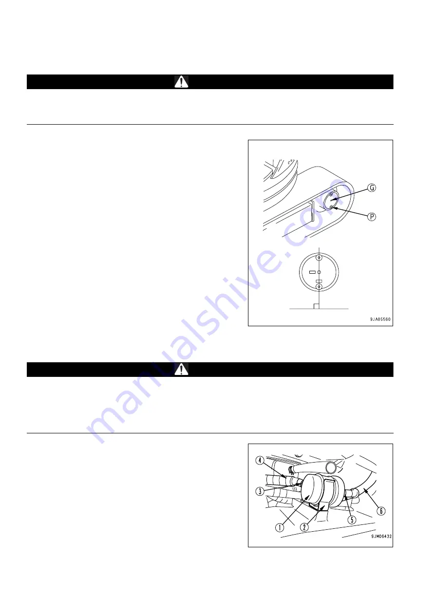
The check must be carried out on each reduction gear, with 
the drain plug (P)  in low position and perpendicular to the 
ground. If necessary, move the machine slightly until reach-
ing the specified position, which is indispensable for an accu-
rate check.

2.

This is a visual check and serves to make sure that the lubri-
cant reaches the height of the hole (G); if this is not the case, 
top up by proceeding as explained in paragraph "4.9.6.b 
CHANGING THE OIL IN THE FINAL REDUCTION GEARS"
and using the oil prescribed in the lubricant chart (see "4.4 
FUEL, COOLANT AND LUBRICANTS")
.

4.9.5.e

CHANGING THE FUEL PUMP PREFILTER

WARNING

q

Change the prefilter after work, when the engine has cooled down to 40÷45°C.

q

During these operations some fuel may be spilled; clean the dirty areas immediately, in order to prevent 
any risk of slipping or fire.

q

Oils, filters, the coolant and the battery are considered special waste and must be collected and dis-
posed of according to the regulations in force.

1.  Prepare a container under the prefilter (1) to gather the fuel.
2.  Remove the prefilter from the clamp (2).
3.

Remove the clamp (3) and disconnect the pipe (4) from the 
prefilter.

4.

Remove the clamp (5), disconnect the pipe (6) from the used 
prefilter and discard it.

5.  Connect the pipes (4) and (6) to a new prefilter and fasten 

them with the clamps (3) and (5).

6.  Install the prefilter in the clamp (2) and bleed the fuel circuit 

(see "4.9.5.c CHANGING THE FUEL FILTER ELEMENT 
(WITH WATER SEPARATOR)").

Summary of Contents for PC26MR-3

Page 1: ...s and maintenance personnel must read this manual before operating or maintaining this machine This manual should be kept inside the cab for reference and periodically reviewed by all personnel who will come into contact with the machine WARNING PC26MR 3 HYDRAULIC EXCAVATOR SERIAL NUMBER PC26MR 3 F00003 and up ...

Page 2: ......

Page 3: ...ntenance operations that have been carried out are important since they provide a clear report on the situation and say exactly what has been done and what has to be done after the next maintenance interval Therefore it is advisable to consult both the hour meter and the mainte nance plan frequently q Over the years Komatsu Dealers have gathered considerable experience in customer service If more ...

Page 4: ... The use of this term must be limited to situations of extreme danger WARNING q Indicates a situation of potential danger that if not avoided may cause serious injury and even death CAUTION q Indicates a situation of potential danger that if not avoided may cause moderate injury This term can also be used as a warning against dangerous interventions Other terms used in the signs In addition to tho...

Page 5: ...dden to modify the setting of the hydraulic system safety valves Komatsu cannot be held liable for any damage to persons property or the machine if this has been tampered with by modi fying the standard settings of the hydraulic system WARNING q Before carrying out any electric welding disconnect the battery and the alternator See 2 8 13 PRE CAUTIONS TO BE TAKEN WHEN HANDLING THE BATTERY AND THE A...

Page 6: ...ine and the hydraulic couplings necessary for the operation of such equipment are grouped in the final section of this manual Komatsu machines are constructed exclusively for the handling excavation and treatment of inert materials there fore the following uses are absolutely forbidden q USE OF THE MACHINE BY MINORS OR INEXPERIENCED PERSONS q USE OF THE MACHINE FOR THE LIFTING OF PEOPLE q TRANSPOR...

Page 7: ...ations and abrupt reversals SYNTHETIC BIODEGRADABLE OIL TYPE HEES For machines in which synthetic biodegradable oil type HEES is used perform the following operations in addition to the standard maintenance operations q After the first 50 hours of operation change the hydraulic circuit drain filter q After the first 500 hours of operation change the hydraulic circuit oil IMPORTANT q When changing ...

Page 8: ...amped on the front upper part of the main frame on the left side 1 4 2 MACHINE IDENTIFICATION PLATE AND PRODUCT IDENTIFICATION NUMBER PIN The Komatsu excavators described in this manual are CE marked in fact they are in compliance with the EU harmonised standards The plate with the CE marking is applied to the front wall of the main frame on the left side RKA01330 RKA01330 RKA01331 RKA01331 RKA181...

Page 9: ...e engine itself The exhaust gas emission plate is applied to the upper surface of the tappet cover and on the rear left side of the cab support frame 1 4 4 TRAVEL REDUCTION GEAR SERIAL NUMBER The serial number is stamped on the plate positioned inside the travel reduction gear and can be seen after removing the cover 1 RKA18110 RKA18120 RKAA0300 1 RKAB6810 1 ...

Page 10: ...SWING REDUCTION GEAR SERIAL NUMBER The serial number is stamped on the plate positioned on the up per side of the swing motor 1 4 6 CAB SERIAL NUMBER The serial number is stamped on the plate positioned on the up per left side RKAB2570 RKAB1750 ...

Page 11: ...CATION WEAM009500 9 1 4 7 SERIAL NUMBERS AND DEALER S ADDRESS Machine no Model Product identification number PIN Travel reduction gear no Swing reduction gear no Dealer Address Tel Contact person NOTES Cab No Engine no ...

Page 12: ...dealer will be in charge of removing and installing the KOMTRAX equipment q Do not flatten or damage the cables or wires Do not pull the cables or wires hard Short circuits and disconnected cables can cause failures or fire in the KOMTRAX equipment or the ma chine q If you have a pacemaker make sure that the communication aerial is placed at least 22 cm from the pacemaker as radio waves can advers...

Page 13: ...F THE SAFETY PLATES 18 2 1 2 PICTOGRAMS AND RELEVANT MEANINGS 19 2 1 3 POSITION OF THE NOISE PLATES ON MACHINES WITH CAB 24 2 1 4 POSITION OF THE NOISE PLATES ON MACHINES WITH CANOPY 25 2 1 5 VIBRATIONS TO WHICH THE OPERATOR IS SUBJECTED 25 2 2 GENERAL PRECAUTIONS 26 2 2 1 GENERAL SAFETY RULES 26 2 2 2 SAFETY DEVICES AND GUARDS 26 2 2 3 CLOTHING AND PERSONAL PROTECTION ITEMS 26 2 2 4 UNAUTHORIZED ...

Page 14: ...2 6 2 STARTING WITH BOOSTER CABLES 48 2 7 PRECAUTIONS FOR THE REMOVAL OF THE MACHINE 49 2 8 PRECAUTIONS FOR MAINTENANCE 50 2 8 1 WARNING PLATES 50 2 8 2 TOOLS 50 2 8 3 MAINTENANCE STAFF 50 2 8 4 EQUIPMENT 51 2 8 5 WORKING UNDER THE MACHINE 51 2 8 6 CLEANING THE MACHINE 51 2 8 7 USE OF THE ENGINE DURING MAINTENANCE 52 2 8 8 PERIODICAL CHANGE OF THE PARTS THAT ARE CRITICAL FOR SAFETY 52 2 8 9 STOP T...

Page 15: ...PS AND COVERS WITH LOCK 88 3 2 6 ENGINE HOOD 89 3 2 7 RADIATOR COVER 90 3 2 8 TANK COVER 91 3 2 9 TILTING THE CAB FLOOR 92 3 2 10 FUSES 96 3 2 11 MAIN FUSE 97 3 2 12 12V OUTLET FUSE 97 3 2 13 TECHNICAL DOCUMENTATION COMPARTMENT 98 3 2 14 TOOL BOX 98 3 2 15 GREASING PUMP SUPPORT 98 3 3 USE OF THE MACHINE AND RELATED CONTROLS 99 3 3 1 BEFORE STARTING THE ENGINE 99 3 3 1 1 VISUAL CHECKS 99 3 3 1 2 CH...

Page 16: ...OCEDURE 147 3 4 2 LOADING AND UNLOADING THE MACHINE 147 3 4 3 LIFTING THE MACHINE 153 3 5 USING THE MACHINE IN THE COLD SEASON 155 3 5 1 PRECAUTIONS TO BE TAKEN WHEN USING THE MACHINE IN THE COLD SEASON 155 3 5 1 1 FUEL AND LUBRICANTS 155 3 5 1 2 COOLANT 155 3 5 1 3 BATTERY 156 3 5 2 CAB VENTILATION AND COOLING 157 3 5 3 PRECAUTIONS TO BE TAKEN EVERY DAY AT THE END OF WORK 158 3 5 4 HOW TO PROCEED...

Page 17: ...C BREAKER 188 4 8 2 a CHANGING THE HYDRAULIC OIL FILTER 188 4 8 2 b CHANGING THE HYDRAULIC OIL 188 4 9 MAINTENANCE PROCEDURES 189 4 9 1 WHEN REQUIRED 189 4 9 1 a CHECKING CLEANING OR CHANGING THE AIR FILTER CARTRIDGE 189 4 9 1 b CAB AIR FILTER CHECK AND CLEANING machines with cab 191 4 9 1 c CHECKING THE BATTERY CHARGE LEVEL 192 4 9 1 d CLEANING THE FUEL FILTER WITH WATER SEPARATOR 193 4 9 1 e DRA...

Page 18: ...218 4 9 7 MAINTENANCE EVERY 2000 HOURS OF OPERATION 219 4 9 7 a CHANGING THE OIL IN THE HYDRAULIC TANK AND CLEANING THE FILTER 219 4 9 7 b CHANGING THE COOLANT 222 4 9 7 c CHECKING THE ALTERNATOR AND THE STARTER 223 TECHNICAL SPECIFICATIONS 5 1 TECHNICAL DATA 226 5 2 LIFTING CAPACITIES 228 5 2 1 LIFTING CAPACITIES WITH CANOPY 228 5 2 2 LIFTING CAPACITIES WITH CAB 230 AUTHORIZED OPTIONAL EQUIPMENT ...

Page 19: ...SAFETY AND ACCIDENT PREVENTION 17 ...

Page 20: ...clean them with a solution made of water and detergent Do not use fuel petrol or solvents q If the plates are damaged ask for new ones to Komatsu or to your Komatsu Dealer q In case of replacement of a component provided with a safety plate make sure that such a plate is applied also to the new part q The machine can be provided with other plates in addition to those indicated below keep also to t...

Page 21: ...hat they look like and their respective meanings WORK IN PROGRESS q Do not approach or stand within the equipment operating range when the boom and the bucket are raised DO NOT OPEN THE ENGINE HOOD q Do not open or remove the hood when the engine is running CONSULT THE MANUAL q Carefully read the contents of the manual before using the ma chine or performing maintenance operations SAFETY DISTANCE ...

Page 22: ...n is cor rectly inserted FRONT WINDSCREEN LOCKING only with cab q Make sure that the front windshield is always locked HYDRAULIC OIL TOPPING UP q Only for machines in which synthetic biodegradable oil type HEES is used BATTERY MAIN SWITCH HYDRAULIC OIL TOPPING UP 22L 98 R2390 09803 A0481 RWA34380 BIO OIL RKA24350 22E 98 21140 RWA00050 ...

Page 23: ...TY NOISE AND VIBRATION PLATES WEAM009500 21 REFUELLING ENGINE OIL FILTER FUEL FILTER ENGINE AIR INTAKE FILTER ENGINE COOLANT ENGINE COOLANT PRESSURE D RWA00040 RWA00080 D RWA00060 RWA00090 RWA00130 RWA00110 ...

Page 24: ...E AND VIBRATION PLATES 22 WEAM009500 HYDRAULIC OIL LEVEL HYDRAULIC OIL FILTER POWER OUTLET ANCHORAGE POINT EMERGENCY EXIT machines with cab LIFTING POINT RWA00100 RWA00070 12 V RWA00120 RWA00200 RWA00190 RWA04920 ...

Page 25: ...2K 98 R2110 3m 2m 1m 0 1m 0 L 1015mm L 1365mm 640kg 585kg 560kg 570kg 555kg 335kg 320kg 310kg 300kg 380kg 265kg 235kg 255kg 350kg 210kg A B 2m 3m MAX W 450mm kg 34 L A B 22K 98 R2110 3m 2m 1m 0 1m 0 L 1015mm L 1365mm 640kg 585kg 560kg 570kg 555kg 335kg 320kg 310kg 300kg 380kg 265kg 235kg 255kg 350kg 210kg A B 2m 3m MAX W 450mm kg 34 ...

Page 26: ... the plates are damaged ask for new ones to Komatsu or to your Komatsu Dealer q In case of replacement of a component provided with a noise plate make sure that such a plate is applied also to the new part EXTERNAL NOISE q This value indicates the noise level outside the machine and re fers to the noise perceived by persons in the vicinity of the work area NOISE INSIDE THE CAB q This value indicat...

Page 27: ...th a noise plate make sure that such a plate is applied also to the new part EXTERNAL NOISE q This value indicates the noise level outside the machine and re fers to the noise perceived by persons in the vicinity of the work area q This value indicates the noise level perceived by the operator when seated in driving position 2 1 5 VIBRATIONS TO WHICH THE OPERATOR IS SUBJECTED q According to the re...

Page 28: ...ep them in good operating conditions q Any improper use of the safety devices may result in serious injury or even death 2 2 3 CLOTHING AND PERSONAL PRO TECTION ITEMS q Do not wear large or loose clothes rings and watches and do not approach the machine with loose long hair since they can get entagled in the moving parts of the machine and cause seri ous injury or damage Avoid also wearing clothes...

Page 29: ...injury or damage caused by unauthorized modifications 2 2 5 LEAVING THE OPERATOR SEAT q When leaving the operator seat even if temporarily make sure that the machine is in a safe position See 2 4 14 PARKING THE MACHINE q Before leaving the operator seat carry out the following opera tions in the sequence indicated below 1 Lower the equipment to the ground 2 Attach the safety devices for boom swing...

Page 30: ...e locked position L 4 Stop the engine See 3 3 3 STOPPING THE ENGINE 5 If you have to go so far away that you will not be able to see the machine extract the ignition key MACHINES WITH CAB On machines with cab there is a single safety lever located to the left of the Operator CAB RKA23380 CAB RKA23390 ...

Page 31: ...e very carefully q Do not hold or rest on the control levers q Both when getting on and when getting off the machine always maintain three points of contact holding or resting points in or der to avoid losing your balance and falling down q Tighten the handle screws if they are loose and clean the han dles and tracks if they are dirty with oil or grease Carefully clean the cab floor if it is dirty...

Page 32: ...or adding oil tighten the fuel or oil cap securely q Do not fill the tank completely in order to leave room for the fuel to expand q In case some fuel is spilled wipe it up immediately 2 2 8 PREVENTING BURNS q If the engine coolant the engine oil and the hydraulic oil are hot use heavy cloths and wear gloves heavy clothing and safety goggles before carrying out any check or touching the hot parts ...

Page 33: ... are not complied with it is forbid den to use the machine 2 2 10 PREVENTING DAMAGE CAUSED BY THE WORK EQUIPMENT q Do not stand within or approach the operating range of the work equipment even when the operator is on board the machine and the engine is running q Do not stand or work under the arms or the articulations when the arms are lifted if you are not sure that the safety locks have been du...

Page 34: ...ure and resistance checked q Do not remove the ROPS canopy for any reason whatsoever and avoid using the machine without canopy q If it is absolutely necessary to remove the ROPS canopy always contact your Komatsu Dealer before carrying out this operation 2 2 13 PRECAUTIONS CONCERNING THE CAB STRUCTURE q If the cab is inadvertently hit or the machine overturns during work the cab may be damaged wi...

Page 35: ...until the end of the operations Be careful not to sever or damage any of these lines q Check the depth and flow of water before operating in water or on river banks 2 3 2 FIRE PREVENTION q Completely remove any wood chips rubbish paper and other flammable materials that may have accumulated inside the en gine compartment since they may cause fires q Check the fuel and hydraulic system pipes for le...

Page 36: ...the lights in such a way as to ensure perfect visibility on the work area q Make sure that the work lights have been correctly installed Make also sure that they come on correctly 2 3 6 CLEANING THE WINDOWS AND CHECKING THE WINDSHIELD WIPER BLADES q Remove any trace of dirt from the cab windows this will optimize visibility q Check the conditions of the windshield wiper blades the scraping wire mu...

Page 37: ... q Do not allow anyone to get on the machine q Open the triangular cover the engine bonnet and the tank hous ing and make sure that the platform no 4 fixing screws 1 are properly tightened If the platform is not properly fixed serious injuries may result If a failure is detected carry out the neces sary repair operations 2 4 2 CHECK THE DIRECTION BEFORE STARTING THE MACHINE q Before operating the ...

Page 38: ...Only one person must be entrusted with making signals q The operator must make sure that the signalman is always within his field of vision and follow all his sig nals The use of hand signals serves to direct the lifting handling and positioning of the loads lifted by the work equip ment Hand signals can also be used during digging operations or when the machine travels if the field of vision of t...

Page 39: ...ected towards the signalman move the hand in the di rection of the movement to be carried out 5 LIFT THE BOOM With an arm extended in horizontal position and closed fin gers point the thumb upwards 6 LOWER THE BOOM With an arm extended in horizontal position and closed fin gers point the thumb downwards 7 SWING THE BOOM With an arm extended in horizontal position point the forefin ger in the desir...

Page 40: ...THE BUCKET Keep one hand still and open Rotate the other hand vertical ly with the thumb pointed towards the open hand 13 TRAVEL WHILE STEERING Lift the forearm corresponding to the inner steering side with clenched fist Rotate the other fist vertically indicating the wheel s turning direction 14 TRAVEL WHILE STEERING Lift the forearm corresponding to the inner steering side with clenched fist Rot...

Page 41: ...ve the hands laterally indicating the distance to be covered 18 CARRY OUT THE MOVEMENTS SLOWLY One hand still in front of the hand that indicates the move ment to be carried out The figure represents the lift slowly control 19 STOP With one arm extended laterally open the hand facing down wards and move the arm forwards and backwards 20 EMERGENCY STOP With both arms extended in horizontal position...

Page 42: ...PRECAUTIONS TO BE TAKEN WHEN WORKING 40 WEAM009500 21 STOP THE ENGINE Pass thumb or forefinger across the throat RKA15340 ...

Page 43: ...possible to evaluate more precisely the space required for the movements and at the same time ensures the stability of the machine q Make sure that the driver seat is directed towards the blade Otherwise pay attention to the steering and advance manoeu vres since they are inverted q If the equipment control levers must be used during travel avoid moving them abruptly sudden manoeuvres change the a...

Page 44: ...w speed When travelling downhill position the machine with the turret rotated by 180 so that the sprocket 1 and the boom are in travelling direction as shown in the figure and proceed at low speed q Do not change direction on slopes side movements must be carried out on level ground or with inclination not exceeding 10 q Do not move on slopes whose inclination exceeds 15 since the machine may over...

Page 45: ...ations are going to last long accumulate soil in such a way as to create a horizontal platform on which the ma chine can be positioned 2 4 8 UNAUTHORIZED OPERATIONS q Do not carry out excavations under overhangs The overhang may collapse and fall on the machine q Do not excavate too deeply under the front of the machine The ground under the machine may collapse and cause the ma chine to fall q To ...

Page 46: ... materials may damage the work equipment or even cause serious personal injury q As a general rule the machine is more liable to overturn when the work equipment is swung to one side than when it is at the front or rear q When using a breaker or other heavy duty equipment the machine may lose its balance and overturn Both when operating on flat ground and when operating on slopes keep to the follo...

Page 47: ...en carrying out this kind of operations warn everyone standing in the work area to keep a safety distance from the machine and the work equipment q Ask the electricity company in advance the voltage of the cables and the minimum safety distance DANGER q The minimum distances from overhead lines can vary in the different countries according to the climate and to the humidity percentage in the air I...

Page 48: ...nes or other material may fall on the machine install the FOPS protection de vice 2 4 14 PARKING THE MACHINE q Park the machine on firm and level ground If this is not possible and it is necessary to park on a slope position the machine with the bucket directed downwards and carry out the following op erations 1 Rotate the bucket to the dumping position and lower the arms until thrusting the teeth...

Page 49: ...h q Position the ramps with a maximum inclination of 15 q Make sure that the surface of the ramps is clean and there is no trace of grease oil soil or ice remove dirt from the tracks be fore loading the machine on the vehicle q The machine must be loaded on the vehicle with the bucket di rected forwards that is in the driving direction of the vehicle q Do not correct the trajectory of the machine ...

Page 50: ...battery stop the engine and remove the ignition key q Avoid short circuiting the battery terminals through any contact even if accidental with metal objects or tools or by inverting them q Tighten the battery terminals securely Loose terminals may generate sparks and may cause the battery to explode 2 6 2 STARTING WITH BOOSTER CABLES q When starting the machine with booster cables always wear safe...

Page 51: ...stride the cable q Move the machine only as far as necessary to allow the re quired repairs to be carried out q Put wooden blocks between the towing cable and the machine body in order to avoid wear or damage q Do not remove the machine in any way other than that indicated in paragraph 3 7 3 REMOVING THE MACHINE CAUTION q The maximum applicable force for the removal is F 2 000 kg for canopy F 2 15...

Page 52: ...d the machine and in particular to the cab door handles 2 8 2 TOOLS q Use only the tools supplied together with the machine and high quality tools suitable for the tasks to be performed q Do not use worn damaged low quality tools or tools that are not suitable for the tasks to be performed in order to avoid any personal injury 2 8 3 MAINTENANCE STAFF q Any maintenance operation must be carried out...

Page 53: ...ease scattered tools or broken pieces are dan gerous because they may cause someone to slip or trip Al ways keep the machine and the work site clean and tidy q To clean the machine use a pressurized jet of warm water or steam and the specific detergents available on the market Do not use diesel oil oil or solvents since the former leave an oily coat that favours the sticking of dust while the latt...

Page 54: ...AL FOR SAFETY q To ensure that the machine can be used as long as possible in total safety it is necessary to add oil and carry out the required maintenance operations at regular intervals To increase safety safety related components like pipes and belts must be periodically changed For the replacement of the parts that are critical for safety see 4 7 PERIODICAL CHANGE OF SAFETY RE LATED COMPONENT...

Page 55: ...unning during mainte nance shift the safety lever 1 to the locked position L and carry out any maintenance operation with the help of another person one operator must remain on board and the words to be used during the operation must be agreed upon in advance NOTE q On machines with cab there is a single safety lever located to the left of the Operator q The person who carries out the maintenance ...

Page 56: ...elling hold the fuel gun firmly and keep it constantly in contact with the filler until you have finished in order to avoid sparks due to static electricity q Do not fill the tank completely in order to leave room for the fuel to expand 2 8 11 CHECKING THE COOLANT LEVEL IN THE RADIATOR q Let the engine and the radiator cool down before checking the coolant level q If it is necessary to remove the ...

Page 57: ...ation reconnect first the positive ca ble and then the negative cable q If electric welding operations are to be carried out on the ma chine it is necessary to disconnect the battery and also the al ternator 2 8 14 PRECAUTIONS CONCERNING THE STARTER q Start the engine only when correctly seated in the driving posi tion q Do not start the engine by tampering with the terminals of the starter since ...

Page 58: ...ent in the tank Small leakages from pipes under pressure and the resulting jets are extremely dangerous since they can perforate the skin and penetrate in the blood circulation or injure the eyes For this reason always wear goggles and thick gloves during the inspections and use a piece of cardboard or a sheet of ply wood to check for oil leakages If you are hit by a jet of high pressure oil or ar...

Page 59: ...ng spring with high preload in order to absorb the im pacts of the front idler roller Do not attempt to remove the spring since this may lead to serious accidents and even death For any operation on the shock absorber unit contact your Komatsu Dealer 2 8 20 HYDRAULIC ACCUMULATOR The hydraulic accumulator contains pressurized nitrogen When carrying out any operation on the accumulator do not pro ce...

Page 60: ... WASTE MATERIALS q Do not dispose of used oil in the sewer system rivers etc q Always put used oil in containers Do not drain exhausted oil di rectly on the ground q Keep to the laws and regulations in force when disposing of harmful substances such as oil fuel solvents used filters and batteries 2 8 23 COMPRESSED AIR q When cleaning the machine or its parts with compressed air flying particles ma...

Page 61: ...es pro duced q In case of contact with the skin immediately rinse with a solu tion made of water and an alkaline detergent for about 30 min utes and then contact a poisoning treatment center without delay 2 8 25 PRECAUTIONS TO BE TAKEN WHEN USING SYNTHETIC BIODE GRADABLE OIL TYPE HEES q It is not possible to mix synthetic biodegradable oil type HEES with ordinary hydraulic oils since when the tem ...

Page 62: ...60 THIS PAGE WAS INTENTIONALLY LEFT EMPTY ...

Page 63: ...THE MACHINE AND ITS OPERATIONS 61 ...

Page 64: ...EAM009500 3 1 MACHINE ILLUSTRATIONS 3 1 1 OVERALL VIEW OF THE MACHINE RKA23420 1 Bucket 7 Track 2 Bucket cylinder 8 Sprocket 3 Arm 9 Undercarriage 4 Arm cylinder 10 Idler roller 5 Boom 11 Blade cylinder 6 Boom cylinder 12 Blade ...

Page 65: ...cking device 22 Hour meter 8 Optional equipment control pedal 23 Engine coolant temperature indicator 9 Travel levers equipped with pedal 24 Engine preheating warning light 10 Boom swing control pedal 25 Electrical system control warning light optional 11 Pedal locking device 26 Engine oil pressure warning light 12 Horn 27 Battery charge level warning light 13 Right work equipment control lever 28...

Page 66: ...that are necessary for correct operation of the machine To perform the required operations correctly and safely it is important to understand the equipment operating methods and the meaning of the information displayed 3 2 1 WARNING LIGHTS AND GAUGES RKA23440 A Emergency lights C Warning lights B Indicators display ...

Page 67: ...y function comes on and the acoustic alarm starts sounding Carry out the necessary re pairs immediately 1 Engine oil pressure warning light This warning light comes on together with the acoustic alarm when the engine is not running and the starting circuit is operated and goes out as soon as the engine lubrication circuit is pressu rized If it does not go out or comes on when the engine is running...

Page 68: ...nd goes out when the en gine exceeds the idling speed if this warning light remains on even when the engine is running at the normal operating speed this means that the alternator is not working and the battery is not charged correctly IMPORTANT q If the warning light remains off when the ignition key is turned to position ON this means that the alternator is faulty or broken ...

Page 69: ...exceeds the set values during operation and reaches the red overheating area B let the engine idle until the indicator returns within the normal operating range A When the indicator reaches the red overheating area B the acoustic alarm sounds and the warning light blinks C If the inconvenience occurs again try to find out if there is any failure see 3 7 6 OTHER TROUBLES RKA23460 1 Engine coolant t...

Page 70: ... B blinks NOTE q If the indicator reaches the red reserve area A during use stop the machine and provide for refuelling 3 Hour meter This instrument indicates the total number of operating hours of the engine The count is continuous and the hour number is in creased by 0 1 when the engine has worked for 0 1 hour 6 min utes independently of the engine speed The hour counter keeps counting even if t...

Page 71: ...d increase warning light This warning light comes on when the travel speed selection switch is in high speed position see 3 2 2 pos 3 Travel speed selection switch When the selector switch is in normal position low speed the warning light on the control box is off NOTE q When the machine travels at high speed on soft ground or up a slope and the load increases the low speed is automatically se lec...

Page 72: ...ilation switch machines with cab 2 Horn 8 Windshield wiper switch machines with cab 3 Travel speed selection switch 9 Overhead light switch machines with cab 4 Working lights switch 10 Power outlet 12V 5 Revolving light switch if installed 11 Battery main switch 6 Boom overload alarm switch if installed RKA23480 ...

Page 73: ...er run As soon as the engine starts release the key which will automatically return to position ON q Position HEAT preheating When starting the engine in cold weather turn the key to posi tion HEAT for approximately 18 seconds until the correspond ing warning light goes out Release the key which will automatically return to position OFF Start the engine by rotating the key to position START IMPORT...

Page 74: ... to low or vice ver sa When high speed is selected the speed increase warning light is lit on the indicators and warning lights display see 3 2 1 3 WARNING LIGHTS When low speed is selected the warning light turns off NOTE q When the engine is started the low speed is automatically se lected When the machine travels on soft ground or up a slope at high speed and the load increases the low speed is...

Page 75: ...tion is disabled 7 Cab heating and ventilation switch machines with cab It is a three speed switch and operates the fan motor Turn the switch 7 clockwise to increase the fan speed When it is activat ed after the cock placed on the heater is opened it causes hot air to circulate performing the heating function See 3 5 2 CAB VEN TILATION AND COOLING The temperature of the air delivered by the heater...

Page 76: ...out Upon release of the switch only the windshield wiper works NOTE q When the windshield washer is in operation pay attention to the following Do not keep the switch pressed in spraying position for more than 10 consecutive seconds Do not press the switch to spray detergent if the reservoir is empty 9 Overhead light switch machines with cab Use this switch 9 to switch on the overhead light q Posi...

Page 77: ...cal current from the battery to the machine electrical system can be interrupted by turning the switch anti clockwise Always interrupt the electrical current before perform ing any operation on the battery or the electrical system and before any welding operations on the machine To restore the electric contact turn the switch clockwise RKAB9750 ...

Page 78: ...7 Boom swing control pedal locking device 2 Left work equipment control lever 8 Boom swing control pedal 3 Right work equipment control lever 9 Cab floor locking lever 4 Accelerator lever 10 Control pedal locking device optional tools 5 Blade control lever 11 Optional equipment control pedal 6 Travel levers equipped with pedal ...

Page 79: ...s This lever operates the safety device that locks the work equipment the swing and travel functions and the attach ments When pulled upwards it is in locked position L The safety device is hydraulic therefore even if the control levers and the pedals move the work equipment and the machine cannot be operated NOTE q If the safety lever on the right or left side is not in the locked position L the ...

Page 80: ...f danger q When the safety lever is in the locked position all the movements are inhibited see 3 2 3 pos 1 Safety lever control locking lever A Version with canopy B Version with cab The control lever 2 is positioned on the operator s left and con trols the arm and the turret swing q Swing function a Swing to the right b Swing to the left q Arm c Fold d Extend N Neutral the turret and the arm are ...

Page 81: ... means reducing consumption and extending the service life of both the engine and the machine 5 Blade control lever It is used to control the movements of the blade a Lower b Lift NOTE q When carrying out digging operations that require the blade to be used for more than one hour without interruption pay atten tion to the engine coolant temperature since this may increase excessively q The transla...

Page 82: ...pedals with the maximum care q When leaving the operator seat always rotate the pedals to the rest position in order to avoid pressing them by mis take These levers are used to operate the travel motors right and left and control the forward and reverse travel according to the move ments indicated a FORWARD levers pushed forward b REVERSE levers pulled towards the operator N Neutral machine at res...

Page 83: ...NT q When the safety lever is in the locked position all the movements are inhibited see 3 2 3 pos 1 Safety lever control locking lever q The boom swing is useful to displace the digging line be yond the track outline do not use this function during the work cycle 9 Cab floor locking lever WARNING q Always keep to the warnings when tilting or closing the cab floor Any operation carried out incorre...

Page 84: ...is inadvertently pressed this may cause serious accidents The safety device is used to lock the optional equipment control pedal 11 Optional equipment control pedal The pedal controls oil delivery to and return from the optional equipment q Upper part of the pedal A pressed The oil flows to the right side of the arm hydraulic tank side q Lower part of the pedal pressed B The oil flows to the left ...

Page 85: ...INDSCREEN machines with cab WARNING q When the upper windscreen or the cab door is opened or closed always take the safety device lever 1 to the lock ing position L If the control levers are not locked and are inadvertently operated there is the risk of serious acci dents q Before opening or closing the windshield stop the ma chine on a level surface lower the work equipment com pletely to the gro...

Page 86: ... at the right or left top of the front wind screen and push the locking levers B down to release the windscreen 5 Seize the handles C and D pull up the windscreen and push it until the lock E is tripped RKAB9680 A B A B RKAB9690 A B RKA22680 RKA21890 RKAB9780 E ...

Page 87: ...ground then stop the engine 2 Shift the safety lever 1 to the locked position L 3 Release the windscreen by means of the upper lock E le ver 4 Seize the handles C and D push the windscreen forwards and lower it slowly 5 When the windscreen lower part reaches the upper part of the lower glass push the windscreen upper section forwards against the locking catches G RKA23830 RKAB9790 E RKA22690 RKA23...

Page 88: ... slope the effort re quired may suddenly change Do not open or close the door on slopes q Be careful to your hands in order to prevent them from be ing caught between the door and the front or centre pillar q If there is anyone inside the cab warn him her before open ing or closing the door IMPORTANT q Always clean the step to access the cab Possible mud or ice accumulation can cause slipping The ...

Page 89: ... or close the window release and draw the handle 1 to slide the window 3 2 4 4 EMERGENCY EXIT HAMMER machines with cab WARNING q When it is necessary to break the window with the hammer pay attention not to get injured by glass chips q Before leaving the operator cab remove any glass frag ments from the window edges and take care not to injure yourself Be careful not to slip on the glass fragments...

Page 90: ...the key clockwise and open the cap Closing 1 Tighten the cap thoroughly and insert the key into the lock 2 Turn the key counterclockwise and extract it OPENING AND CLOSING THE COVERS WITH LOCK Opening 1 Insert the key into the lock 2 Turn the key counterclockwise and open the cover by pulling the grip Closing 1 Close the cover and insert the key into the lock 2 Turn the key clockwise and extract i...

Page 91: ...y and make sure that it is kept open by the apposite rod q Non compliance with these rules may lead to serious accidents IMPORTANT q If it is not necessary to open the cover always keep it locked q When the hood is locked the handle 2 cannot move OPENING THE BATTERY COVER 1 Release the engine hood lock 1 see 3 2 5 CAPS AND COVERS WITH LOCK 2 Pull the handle 2 of the engine hood 3 and open it com p...

Page 92: ...TERY COVER 1 Open the engine cover 1 for details see paragraph 3 2 6 ENGINE HOOD 2 Pull the lever 2 that opens the radiator cover 3 3 Open the cover completely 3 and make sure that it is kept open by the apposite rod 4 CLOSING THE COVER 4 Lift the rod 4 and close the cover 3 without exerting too much pressure When the rod comes out of the groove close the cover completely 5 Close the engine hood 1...

Page 93: ...intenance operations q Carefully check the direction of the slot to make sure that the cap is locked 1 Release the lock of the cap 1 and remove it then remove the gasket 2 For further details see 3 2 5 CAPS AND COVERS WITH LOCK 2 Loosen the four screws 3 and remove the tank cover 4 3 After installing the tank cover 4 make sure that the screws 3 have been correctly tightened and put back the gasket...

Page 94: ...ething wrong in the locking function when the cab floor is tilted interrupt work and have the necessary repairs carried out by your Komatsu Dealer q Do not remove the canopy The cab floor may tilt suddenly q Do not remove the fastening screws 1 of the cab floor since this may tilt suddenly q After lifting the platform always attach the safety stop q Do not carry out any operation on the machine wi...

Page 95: ...he triangular cover 3 6 Open the engine hood 4 completely and make sure that it is kept open by the apposite rod for further details see 3 2 6 ENGINE HOOD 7 Open the radiator cover 5 completely and make sure that it is kept open by the apposite rod for further details see 3 2 7 RADIATOR COVER 8 Loosen the fastening screws of the cab floor 6 9 J A 0 5 4 6 6 ...

Page 96: ...ition Pull the handle 9 backwards with your right hand then re peat the procedure described above q When tilting or closing the cab floor be extremely careful and keep away from the area under the cab floor NOTE q The cab floor tilts thanks to the operation of a gas cylinder so when the ambient temperature is low the operating effort in creases 10 After tilting the floor open make sure that the lo...

Page 97: ...se lever 8 in the direction shown by the arrow backwards with your left hand and at the same time pull the handle 9 downward in the direction indicated by the arrow approximately 45 IMPORTANT q Lower the cab floor slowly and make sure that the wires and pipes located under it are neither damaged nor twist ed q When tilting or closing the cab floor be extremely careful and keep away from the area u...

Page 98: ...lved RKA23680 POSITION COLOUR CAPACITY CIRCUIT INVOLVED F1 Red 10A Working headlamp on boom 25A Working headlamp on boom and cab headlamps optional F2 Red 10A PPC solenoid valve horn fuel supply pump start up antirepetition re lay overload pressure switch F3 Red 10A Indicators and warning lights display buzzer speed increase solenoid valve PPC relay F4 Red 10A Start up blocking relay komtrax servi...

Page 99: ...he machine to check the fuse and change it if neces sary The mains fuse 50A is located above the battery For de tails on how to open and close the right cover see 3 2 7 RADIATOR COVER NOTE q The main fuse is the high capacity fuse installed to protect the electric components and the wiring 3 2 12 12V OUTLET FUSE IMPORTANT q When changing a fuse make sure that the ignition key is in position OFF Th...

Page 100: ...14 TOOL BOX The tool box is positioned inside the seat support and can be reached by opening the front panel 3 2 15 GREASING PUMP SUPPORT WARNING q Soon after the engine has stopped the temperature of the components is very high and may cause burns Wait for the temperature to become lower before carrying out the greasing procedure The grease pump support is positioned in the upper internal part of...

Page 101: ...owing inspection and cleaning operations every day before starting the engine 1 Check the work equipment the cylinders the articulations and the pipes for damage wear excessive play If any anomaly is observed provide for the necessary re pairs 2 Remove dirt and dust from around the engine the battery and the radiator Check that there is no dirt or dust accumulated around the engine or the radiator...

Page 102: ... surface 8 Check the seat belt and the relevant couplings If there is any damage or anomaly change them with new ones 9 Check the cab floor fastening screws Open the engine hood and make sure that the 4 fastening screws of the cab floor 1 are correctly tightened If there are loose screws tighten them If any anomaly is observed carry out the necessary repairs or have them carried out by your Komats...

Page 103: ...the cap in these conditions to check the coolant level may cause a burn hazard Before removing the cap wait until temperature is reduced and loosen the cap slowly to release the remaining pressure 1 Open the engine hood and the radiator cover For details see paragraph 3 2 7 RADIATOR COVER 2 Make sure that the coolant level is included between the FULL and LOW marks on the expansion tank 1 If the l...

Page 104: ...ed before checking the engine oil level wait approximately 15 minutes in order to allow the engine to cool down 1 Open the engine hood For details see paragraph 3 2 6 EN GINE HOOD 2 Remove the dipstick G and wipe it with a cloth 3 Insert the dipstick G completely into the oil filler pipe then remove it and check the oil level 4 Oil level must be between references H and L if the oil level is close...

Page 105: ...heck the fuel level on the fuel gauge 2 If the level is low unlock the lock remove the cap and top up through the filler F While refuelling check the fuel level on the sight gauge G Tank capacity 28 l 3 Avoid filling the tank completely and leave enough space for the fuel to expand 4 After refuelling tighten the cap thoroughly and lock it IMPORTANT q It is advisable to refuel after work in order t...

Page 106: ...the engine hood and the radiator cover For details see paragraph 3 2 7 RADIATOR COVER 3 Make sure that the oil level is included between the H and L marks on the sight gauge G IMPORTANT q Do not exceed the max level mark H This would damage the hydraulic circuit and cause the oil to overflow q If too much oil is added and this exceeds the level H on the gauge turn the turret so that the drain plug...

Page 107: ...ump for leaks CHECKING THE AIR FILTER CLOGGING INDICATOR 1 Open the engine hood For further details see paragraph 3 2 6 ENGINE HOOD 2 Check if the red piston is visible in the transparent portion of the filter clogging indicator 1 3 If the red piston is visible clean or replace the filtering ele ment immediately For further details on how to clean the filtering element see 4 9 1 a CHECKING CLEANIN...

Page 108: ...1 is floating this means that there is water up to its lower surface therefore drain the water by proceeding as follows 1 Open the engine bonnet and move the lever 3 to the locking position A For details see 3 2 6 ENGINE HOOD 2 With the filter wrench loosen the ring nut 4 then remove the container 2 and eliminate the water accumulated inside it 3 Put back the casing 2 and tighten the metal ring 4 ...

Page 109: ...ure that the charge level warning light is always visi ble Make sure that the fuses are not damaged that fuses with the required capacity are used that there are no dis connected broken or short circuited wires furthermore check the terminals and tighten any loose ones Check the wiring of the battery the starter and the alternator carefully In addition remove any flammable material that may have a...

Page 110: ... carrying out deep digging opera tions make the seat slide forward to improve visibility on the low er area in front of the machine B Suspension In order to adjust the suspension turn the handwheel 2 placed on the rear side of the seat until the ideal springing for the opera tor is obtained Turn the handwheel anticlockwise to soften the suspension sign on the handwheel turn it clockwise to harden ...

Page 111: ... RELATED CONTROLS WEAM009500 109 REAR VIEW MIRRORS Adjust the inclination of the rear view mirrors so that the area behind the cab is well visible q Machine equipped with canopy q Machine equipped with cab RKA23720 RKA23730 ...

Page 112: ...ary apply a tightening torque of 24 5 4 9 Nm 2 5 0 5 kgfm If the surface of the belt is damaged or if the couplings are broken or deformed change the belt assembly Fastening and unfastening the seat belt 1 Adjust the seat in such a way as to ensure that there is suffi cient knee room when pressing the pedal thoroughly while seated with the back resting against the backrest 2 After adjusting the se...

Page 113: ... switch 2 and turn it to ON then carry out the checks indicated below 1 Check that the horn goes on for about 1 second and that the following warning lights are on for about 3 seconds Pre heating warning light 3 Battery charge level warning light 4 Engine oil pressure warning light 5 Electrical system control warning light 6 optional Engine coolant temperature warning light 7 Fuel level warning li...

Page 114: ...ght switch 10 and make sure that the working headlamp on the boom turns on If it does not turn on contact a Komatsu Dealer who will carry out all the nec essary repair operations 3 Press the horn button 11 to make sure that the horn functions correctly RKA23770 RKA23780 ...

Page 115: ...ed seat belt q Before starting the engine make sure that there is no one within the operating range of the machine and sound the horn q Exhaust gas is toxic When starting the engine in closed places make sure that there is sufficient ventilation IMPORTANT q Do not make the starter run for more than 20 seconds without interruption If the engine does not start wait at least 2 minutes before trying a...

Page 116: ...en fires q Start the engine only while seated with fastened seat belt q Before starting the engine make sure that there is no one within the operating range of the machine and sound the horn q Never use starting aid fluids as they may cause explosions q Exhaust gas is toxic When starting the engine in closed places make sure that there is sufficient venti lation IMPORTANT q Do not make the starter...

Page 117: ...make sure that the preheating warning light 4 comes on After approximately 18 seconds the warning light 4 goes out indicating that the preheating phase has been completed 4 When the preheating warning light 4 goes out turn the ignition key 3 directly to position START to start the engine 5 As soon as the engine starts release the key 3 which will automatically return to position ON RKA23840 RKA163...

Page 118: ... out the warming up procedure correctly 3 3 2 1 RUNNING IN CAUTION q Komatsu machines are adjusted and tested completely before shipment However operating the ma chine under severe conditions at the beginning can adversely affect the performance of the machine and shorten its life It is advisable to run in the machine for the first 100 hours of operation as indicated by the hour meter During the r...

Page 119: ...r increase the speed up to an interme diate value After starting the engine let it warm up before starting work Carry out the operations and checks indicated below 1 Shift the accelerator lever 1 from the idling A to the inter mediate speed position B and let the engine idle at medium speed for at least 5 minutes NOTE q When the ambient temperature is below 0 C let the engine run at low idling spe...

Page 120: ...t 6 warning light off Battery charge level warning light 7 warning light off 5 Make sure that the colour of the exhaust gases is normal and that there are no strange noises or vibrations If any anomaly is observed contact your Komatsu Dealer 6 Shift the safety lever 2 to the locked position L then make sure that the machine does not move even when the levers and pedals are operated 1 The work equi...

Page 121: ...e recommended not to stop the engine suddenly if it has been running for a long period and is still hot in this case let the engine run at low idling speed for about 5 minutes in order to allow it to cool down gradually before stopping it 1 Run the engine at low idling speed for about 5 minutes in order to allow it to cool down gradually 2 Turn the ignition key 1 to position OFF to stop the engine...

Page 122: ...ke sure that there are no persons other equipment or ob stacles in the way q Avoid any travel manoeuvre or change of direction with the accelerator at maximum speed since ma noeuvres carried out in these conditions may cause abrupt and dangerous movements q Do not use the speed increase function when changing direction or carrying out a counter rotation q Make sure that the travel alarm functions ...

Page 123: ...or vice versa takes place whenever the switch is pressed q When the machine is travelling at high speed the travel speed increase warning light 5 comes on For details on the travel speed see paragraph 5 1 TECHNI CAL DATA NOTE q When the engine is started the low speed is automatically selected When the machine travels at high speed on soft ground or up a slope and the load increases the low speed ...

Page 124: ... of the machine pull the levers 3 slowly backward to start moving in reverse q When the sprocket A is at the front of the machine push the levers 3 slowly forward to start moving in reverse 4 Change the travel speed by proceeding as follows Press the translation speed selector switch 4 positioned on the blade control lever grip to go from low to high trans lation speed and vice versa The changeove...

Page 125: ...ses the low speed is automatically selected but the travel speed increase warning light remains on When the load is reduced the travel system automatically changes over to high speed 5 Make sure that the travel alarm functions correctly If the alarm does not sound contact your Komatsu Dealer which will carry out the necessary repairs 3 3 4 4 STOPPING THE MACHINE WARNING q Avoid stopping the machin...

Page 126: ... speed and the load increases the low speed is automatically selected and the machine slows down When the load is reduced the travel system automatically changes over to high speed Use the travel levers to change direction Avoid abrupt changes of direction as much as possible In particu lar when carrying out a counter rotation stop the machine before steering Operate the two travel levers 1 as fol...

Page 127: ...to the left NOTE q To steer to the right operate the right travel lever in the same way HOW TO CARRY OUT COUNTER ROTATIONS SPIN TURN To carry out a counter rotation to the left pull the left travel lever backward and push the right travel lever forward NOTE q To carry out a counter rotation to the right pull the right travel lever backward and push the left travel lever forward RYA02170 RYA02180 ...

Page 128: ... left work equipment control lever 1 2 When the swing function is not used shift the left lever 1 to the neutral position N With the lever in this position the swing lock is automatically engaged NOTE q When the turret swing function is used on a slope let the engine idle and operate the swing control lever very slowly Take care to avoid abrupt movements when the bucket is full RKA23940 N RYA02200...

Page 129: ...lly return to the neutral position and the work equipment remain in the position where they stopped The movements of the levers and the corresponding movements of the equipment are shown in the diagrams be low q 2nd boom control To activate the 2nd boom move the left lever forwards or backwards q Swing control To turn the turret move the left lever to the left or right q 1st boom control To activa...

Page 130: ...ATED CONTROLS 128 WEAM009500 q Boom swing control To swing the boom use the boom swing control pedal q Blade control Shift the lever positioned to the right of the operator seat forward or backward to operate the blade RKA23950 ...

Page 131: ...EL FORCE OF THE MACHINE Do not dig the bucket into the ground and do not use the travel force to carry out digging operations This may damage the ma chine or the work equipment q PRECAUTIONS TO BE TAKEN WHEN USING THE HYDRAU LIC CYLINDERS When using the machine do not reach the end of stroke with the cylinders but always leave a safety margin If the cylinders reach the end of stroke excessive forc...

Page 132: ...IT IS NOT ALLOWED TO EX PLOIT THE FORCE OF GRAVITY OF THE MACHINE Do not use the force of gravity of the machine to carry out dig ging operations When working on hard rocky surfaces use some other method to break the rock into small pieces before excavating This avoids any damage to the machine and is also more economi cal q SUPPORT THE MACHINE WITH BOTH SIDES OF THE BLADE When using the blade as ...

Page 133: ...nd and try to move the machine keeping the obsta cle equidistant from the tracks q FOLDING THE WORK EQUIPMENT When folding the work equipment to the travel or transport posi tion be careful to prevent the bucket from hitting the blade q AVOID HITTING THE BLADE Be careful not to hit the blade against rocks or boulders since this may damage the blade or the cylinders q POSITION OF THE BLADE DURING D...

Page 134: ... the turret will be sub merged and this may cause the cooling fan to break Be extremely careful when driving the machine out of wa ter Do not immerse the machine in water beyond the permissible depth under the carrier roller 1 Furthermore when a component has been immersed in water for a long time pump in grease until the old grease comes out of the bearings around the bucket pins ...

Page 135: ... or down steep slopes since the machine may overturn q During travel lift the machine at about 20 30 cm from the ground Do not travel downhill in reverse q Do not change direction on slopes side movements must be carried out on level ground or with inclination not ex ceeding 10 q Always operate the machine or travel in such a way as to be able to stop it safely at any time if it slips or becomes u...

Page 136: ...If the engine stops when the machine is travelling uphill shift the travel levers to the neutral position lower the bucket to the ground stop the machine then start the engine again PRECAUTIONS TO BE TAKEN ON SLOPES q If the engine stops when the machine is on a slope do not use the left work equipment control lever to swing the turret The turret will swing due to its own weight q Do not open or c...

Page 137: ...ush with the bucket teeth The angle between the boom and the arm should be included between 90 and 110 When only one side gets stuck in mud use the bucket to raise the track then lay boards or logs under the track and drive the ma chine out BOTH TRACKS STUCK IN MUD If both tracks are stuck in mud and the machine slips and cannot move put logs or wooden blocks under the machine proceeding as indica...

Page 138: ...e from a 45 angle away from the machine to a 30 angle towards the ma chine There may be some differences depending on the digging depth but it is advisable to try to keep within the above range rather than operate with the cylinders reaching the end of stroke DITCH DIGGING Ditch digging operations may be effectively carried out by install ing a bucket suitable for this type of digging and position...

Page 139: ...09500 137 FILLING LEVELLING OPERATIONS Use the blade to refill after excavation or to level the ground sur face SIDE DITCHING WORK The machine can be used for side ditching in confined spaces by combining the turret swing and boom swing functions ...

Page 140: ...vements q The described procedures are valid also for the coupling of the mechanical connections of the optional equipment 1 Position the bucket on level ground directing it so that the flat part of its back rests on the ground 2 Remove first the tie rod pin 1 and then the arm connection pin 2 3 Change the bucket taking care to clean the pins the bush ings and the seals perfectly and to grease the...

Page 141: ...racks and thrust the work equipment into the ground to prevent the machine from moving q If the control levers are inadvertently touched the work equipment or the machine may move suddenly and cause serious accidents Before leaving the operator seat shift the safety lever to the locked position q Position the blade facing downhill and lower it to the ground 1 Shift the right and left travel levers...

Page 142: ...the engine off check the engine water temperature in the indicator 1 the engine oil pressure warning light 2 and the fuel level in the indicator 3 3 3 16 CHECKS TO BE CARRIED OUT AFTER WORK 1 Walk around the machine check the work equipment the outside of the machine and the undercarriage and make sure that there are no oil or coolant leakages If any anomaly is observed provide for the necessary r...

Page 143: ...ock the following parts 1 Cab door machines with cab Always close the windows 2 Engine hood 3 Fuel filler cap 4 Document and tool compartment cover For further details see paragraph 3 2 5 CAPS AND COVERS WITH LOCK NOTE q Use the ignition key to open and lock the door caps and covers RKA24000 ...

Page 144: ...take the necessary precautions for use and to avoid performing operations that are not allowed This will in crease the life of the rubber tracks and will allow their characteristics to be fully exploited Before using the rubber tracks read paragraph 3 3 18 3 USE OF THE RUBBER TRACKS 3 3 18 2 WARRANTY ON RUBBER TRACKS It is important to carry out inspections and maintenance operations and to ensure...

Page 145: ...ith considerable differences in height When moving on obstacles or surfaces with considerable differences in height position the machine perpendicular to the obstacle to prevent the tracks from coming off q If the machine has been raised using the bucket lower it slowly q Avoid using the machine to handle materials that once crushed produce oil like soy maize or other vegetable parts from which oi...

Page 146: ...pe If this is absolutely necessary carry out the manoeuvre grad ually 3 Avoid traveling along the edge of slopes or on rough ground with one track raised machine inclination exceeding 10 and with the other track on flat ground To avoid damaging the rubber tracks always proceed with both tracks resting on the same horizontal plane 4 If the machine is operated in the conditions described in points f...

Page 147: ...more if the machine travels in reverse a gap is formed between the carrier roller the idler roller and the track The rubber track may come off also in the following conditions q When turning in a condition where the rubber track cannot move laterally due to the obstacle over which it is passing or because of any other obstacle q When the rubber track is not aligned and the idler roller or the carr...

Page 148: ...NE AND RELATED CONTROLS 146 WEAM009500 q If the machine travels in reverse in these conditions the rubber track will come off q If the machine steers in these conditions the rubber track will come off RYA02820 RYA02830 ...

Page 149: ... C When us ing piled soil compact it to prevent the inclined surface from collapsing q Before loading the machine remove any trace of mud and dirt from the tracks in such a way as to prevent the ma chine from slipping when it is on the ramps Make sure that the surface of the ramps is clean and that there are no trac es of water snow ice grease or oil q Do not change direction when the machine is a...

Page 150: ... the road 2 Activate the trailer brakes and position safety blocks under the wheels to be sure that the trailer does not move Ramp inclination must not exceed 15 3 Run the engine at low speed A Idling 4 Make sure that the travel speed increase warning light is off NOTE q If the warning light is on press the translation speed selector switch located on the blade control lever grip The warning light...

Page 151: ...he ramps and that the centerline of the machine corresponds to the centerline of the trailer The machine must move slowly and its travelling direction must correspond to the direction of the ramps Lower the work equipment as much as possible without causing any interference When the machine is on the ramps operate only the travel levers Do not operate any other lever 7 Stop the machine where requi...

Page 152: ...afety lever to the locked position L NOTE q On machines with cab there is a single safety lever located to the left of the Operator 5 Lock the cab door and cases with lock see section 3 2 5 CAPS AND COVERS WITH LOCK IMPORTANT q Do not use the hole in the back of the undercarriage to tow or lift the machine 6 Place blocks under both ends of the tracks to prevent the machine from moving during trans...

Page 153: ...at the trailer does not move Ramp inclination must not exceed 15 3 Remove the chains and the metal cables with which the machine has been secured 4 Start the engine and let it warm up completely 5 Make sure that the travel speed increase warning light is off NOTE q If the warning light is on press the translation speed selector switch located on the blade control lever grip The warning light will ...

Page 154: ... engine at low speed A Idling 8 Lift the blade 9 Raise the work equipment make sure that the travelling di rection of the machine corresponds to the direction of the ramps and proceed slowly Lower the work equipment as much possible without caus ing any interference When the machine is on the ramps operate only the travel levers Do not operate any other lever or pedal RKA23870 RKA23860 RKA23970 ...

Page 155: ...e This would damage the cab q It is prohibited to lift the machine using the holes provided in the undercarriage since these must be used only for transporting the machine This would damage the under carriage IMPORTANT q For details on the weight of the machine see paragraph 5 1 TECHNICAL DATA q The lifting procedure is valid for machines with standard specifications The lifting method varies depe...

Page 156: ... blade 2 points then pass the wire cables through them 8 Install one shackle in the lifting hole provided in the boom then pass the metal cable through it IMPORTANT q Always use the three coupling points provided for lifting the machine Do not lift the machine with swung boom or turret q Pay attention to thecables and take care that they do not get caught 9 Arrange the wire cable so that the lifti...

Page 157: ...r the skin In case of contact with the eyes or the skin wash with plenty of running water and consult a doctor without delay The coolant containing antifreeze is flammable do not smoke and do not use naked flames during the checks and when preparing the mixture 1 Use only Komatsu original coolant antifreeze AF NAC to dilute according to the minimum atmospheric tem perature indicated in the table i...

Page 158: ...acity of the battery decreases accordingly If the battery charge is low the electrolyte may freeze Keep the battery charge level as high as possible and insulate the battery against excessively low temperatures in such a way as to be able to start the machine easily when starting work in the morning NOTE q Measure the coolant weight density and check the battery charge percentage using the followi...

Page 159: ...ng and defogging the glasses Together with the fan there is a radiator that transfers heat to the air sent into the cab it is used during the cold season and re ceives the hot water necessary for exchange heat directly from the engine cooling system The water flow is limited or interrupted by a cock controlled by the knob 3 Turning the handwheel clockwise to increase the hot water flow intensity C...

Page 160: ...position it on wooden boards to prevent the tracks from freezing on the ground which would make it extremely difficult to start the machine the following morning q Open the drain valve and drain the water accumulated in the fuel system to prevent it from freezing q After working in water or mud remove the water from the undercarriage by proceeding as indicated below in or der to extend the life of...

Page 161: ... A PERIOD OF INACTIVITY WARNING q If it is necessary to carry out a rust prevention treatment while the machine is kept indoors open doors and windows to increase ventilation and avoid poisoning by gas When the machine is not used start the machine once a month following the steps below q Recharge the battery and install it on the machine q Start the engine and make some movements with the working...

Page 162: ...is lowered with no load the bucket speed drops momentarily according to the more or less horizontal position of the bucket teeth q When the swing is operated or locked the brake valve emits a noise q When the machine travels down a steep slope at low speed the travel motor brake valve emits a noise 3 7 3 REMOVING THE MACHINE WARNING q When removing the machine use a metal cable suitable for the we...

Page 163: ...o not smoke and avoid producing sparks near the battery q The battery electrolyte is made of diluted sulphuric acid that may corrode clothes and even the skin in case of con tact with this fluid immediately rinse the involved part with plenty of water If the acid gets into the eyes immediately rinse with plenty of water and consult a doctor without de lay q When working on the battery always wear ...

Page 164: ...battery from the machine position it in a well ventilated place and remove the caps before proceeding q Immediately change any damaged caps q Set the voltage of the battery charger so that it corresponds to the voltage of the battery to be charged If the voltage is not set correctly the battery charger may overheat and cause an explo sion q Connect the positive clamp of the battery charger to the ...

Page 165: ...the clamps with each other or with the machine frame IMPORTANT q The booster cables and the clamps must be sized according to the dimensions of the battery q The battery to be used to start the engine must have greater capacity or at least the same capacity as the battery of the machine to be started q Make sure that cables and clamps are neither corroded nor damaged q Make sure that cables and cl...

Page 166: ...BOOSTER CABLES When the engine has started remove the cables in the reverse order with respect to their connection 1 Remove the clamp of booster cable B from the engine block of the machine to be started 2 Remove the other clamp of booster cable B from the nega tive terminal of the machine used as starting aid 3 Remove the clamp of booster cable A from the positive terminal of the machine used as ...

Page 167: ... go out even with engine running Faulty alternator Faulty cables Change Check and repair Alternator emits abnormal noise Faulty alternator Change Starter does not turn with ignition switch in position ON Faulty cables Battery charge insufficient Faulty fuse Check and repair Charge battery Change Starter pinion engages and disengag es repeatedly Battery charge insufficient Charge battery Starter ma...

Page 168: ... joints Engine oil pressure sensor faulty Restore level See CHECKS TO BE CARRIED OUT BEFORE START ING THE ENGINE Replace cartridge See Every 500 hours OF OPERATION Check and repair Change Steam comes out of radiator top pres sure valve Fluid level low fluid leakages Fan belt slack Mud or limestone accumulated in cooling system Radiator fins damaged or closed Faulty thermostat Radiator cap loose wo...

Page 169: ...SYSTEM Adjust valve clearance Exhaust gases white or light blue Too much oil in oil pan Unsuitable fuel Restore level See CHECKS TO BE CARRIED OUT BEFORE START ING THE ENGINE Change with fuel in compliance with standards Exhaust gases occasionally tend to be black Air filter clogged Faulty nozzle Faulty compression Clean or repair See WHEN RE QUIRED Change See above faulty compression Combustion n...

Page 170: ...168 THIS PAGE WAS INTENTIONALLY LEFT EMPTY ...

Page 171: ...MAINTENANCE 169 ...

Page 172: ...and changing filters soon after work is dangerous wait for the engine to cool down to a safe temperature of 40 45 C If it is necessary to drain the oil when it is cold warm it up to a suitable temperature approximately 20 40 C be fore draining it q When changing oils or filters check if metal particles are present If there are large quantities of metal particles contact your Komatsu Dealer q If th...

Page 173: ...oroethylene to clean it Trichloroethylene reduces the resistance and duration of the tank q Before starting work on muddy ground under rain or snow on seashores or river banks check the tightening of valves and caps Wash the machine immediately after work in order to prevent its components from rusting Make sure that there are no damages missing or loose nuts or pins Lubricate the components more ...

Page 174: ...ck of the degree of pollution of the oil 3 periodical change q When changing the oil change also the filters q It is advisable to have the oil periodically analysed in order to check the conditions of the machine The analysis must be carried out by specialized personnel at Komatsu Dealers ITEM TANK SYSTEM SPECIFICATIONS Engine oil SAE 10W 30 Specifications API CF CF2 CD Hydraulic system oil SAE 30...

Page 175: ...ration according to the mini mum atmospheric temperature For concentration see 4 4 1 COOLANT q The coolant containing antifreeze is flammable do not use naked flames near the coolant and do not smoke while topping up q Use only Komatsu original permanent antifreeze coolant AF NAC an ethylene glycol based solution with anti corrosive and antifoam products compatible with aluminium radiators q The u...

Page 176: ...ice is very useful and allows customers to save money and avoid many problems KOWA ANALYSIS STAGES q Analysis of metal particles In this stage a ICP Inductively Coupled Plasma analyser is used to measure the density of the metal particles present in the oil q Measurement of particle quantity In this stage a PQI Particle Quantifier Index machine is used to measure the quantity of large iron particl...

Page 177: ...TERS q Filters are very important components for safety They prevent any impurities from getting into the oil fuel or in the air circuits thus avoiding problems to important components of the machine Periodically change all the filters For further information see the relevant Use and Maintenance manual However when working in extreme conditions it is necessary to change the filters more frequently...

Page 178: ...intenance operations required for the hydraulic system are the following 1 Daily check of the oil level in the tank 2 Periodical change of the oil filter 3 Periodical change of the oil and cleaning of the intake filter q Always bleed the circuit after changing the oil filter or the oil q When a component is removed from the circuit check the gaskets and O rings and change them if they are dam aged...

Page 179: ...cate also the machine serial number to the Komatsu Dealer in or der to receive the most updated version of the component required 4 3 1 LIST OF THE PARTS SUBJECT TO WEAR The parts between parenthesis must be replaced at the same time Part Code Description Qty Change interval Engine oil filter YM119305 35151 Cartridge 1 EVERY 500 HOURS OF OPERATION Fuel filter with water separator YM119810 55650 YM...

Page 180: ...APACITY l 1st filling Change Engine oil pan OIL API CD 3 7 3 4 Travel reduction gears 0 6 0 6 Hydraulic system 29 16 e Hydraulic system with biodegrada ble oil See par 4 4 2 29 16 Fuel tank DIESEL OIL 28 Engine cooling system PERMANENT COOLANT 3 Greasing GREASE Lithium EP MoS2 NLGI 2 30 20 10 0 10 20 30 40 50 C 22 4 14 32 50 68 86 104 122 F SAE 30 SAE 10W 30 SAE 10W SAE 15W 40 SAE 30 SAE 10W SAE 1...

Page 181: ...e components and pipes Oil change quantity quantity of oil necessary to fill the system or unit during the normal inspection and mainte nance operations ASTM American Society of Testing and Materials SAE Society of Automotive Engineers API American Petroleum Institute NLGI National Lubricant Grease Institute EN European Norm 4 4 1 COOLANT Use only original Komatsu coolant AF NAC which should be di...

Page 182: ...e engine the trans missions the braking system etc q Before introducing biodegradable oil in the hydraulic system drain the system completely disconnect ing the cylinders and all the parts that may contain traditional oil then change the drain filter with a new one Start the engine and let it idle before using the equipment wait for the engine temperature to reach at least 40 C then start moving t...

Page 183: ...RTANT q This tightening torque table is not valid for screws or nuts that must fasten parts made of nylon or simi lar materials onto washers or components made of nylon or nonferrous metals or requiring specific tightening torques RYA02980 Thread diame ter a mm Pitch mm Wrench size b mm 8 8 10 9 kgm Nm kgm Nm 6 8 10 12 14 1 1 25 1 5 1 75 2 10 13 17 19 22 0 96 0 1 2 3 0 2 4 6 0 5 7 8 0 8 12 5 1 9 5...

Page 184: ...e a hose always use Komatsu original spare parts having the same size of the part to be replaced a Nm Newton metre 1 Nm 0 102 kgm RKA12600 a Thread diameter a Wrench size mm TIGHTENING TORQUE kgm Nm 9 16 18 11 16 16 13 16 16 1 14 1 3 16 12 1 7 16 12 1 11 16 12 2 12 17 22 24 30 36 41 50 57 2 3 2 5 3 4 3 9 5 2 5 8 8 2 9 2 12 2 13 3 15 3 17 3 18 4 20 4 20 4 24 4 23 25 33 38 51 57 80 90 120 130 150 17...

Page 185: ...TION q The type of lubricant to be used is indicated in the lubricant table see 4 4 FUEL COOLANT AND LUBRI CANTS 10 9 8 2 7 6 5 4 3 15 16 17 18 21 12 11 13 500 h 1 22 1 2 10 h 2000 h 13 1000 h 14 20 19 PC26MR 3 RKA24030 2A1 98 11110 1 13 2 10 3 4 20 19 21 22 5 7 8 6 9 14 16 15 17 18 11 12 Grease Oil Filter BALL BEARING RING GREASING POINT RKAB6820 ...

Page 186: ...ot elapsed yet If the pipe clamps show signs of deterioration like deformations or cracks provide for changing them together with the pipes In addition to the periodical change of the components listed in the following page the inspections described be low are to be carried out on the hydraulic pipes Whenever anomalies are detected carry out the necessary ad justment operations and replacements or...

Page 187: ...pe fuel pump fuel filter 1 4 Fuel pipe fuel filter injection pump 1 5 Fuel pipe fuel filter fuel tank 1 6 Fuel return pipe fuel filter injection pump 1 7 Fuel return pipe between the nozzles 2 8 Fuel return pipe nozzles injection pump 1 9 Fuel return cap 1 10 Hydraulic pipe main pump suction 2 11 Hydraulic pipe main pump delivery 4 12 Hydraulic pipe boom cylinder 4 13 Hydraulic pipe boom cylinder ...

Page 188: ...CREEN WIPER CHECK 205 n BLEEDING THE HYDRAULIC SYSTEM 205 MAINTENANCE AFTER THE FIRST 50 HOURS OF OPERATION Only for ma chines in which synthetic biodegradable oil type HEES is used a CHANGING THE HYDRAULIC OIL FILTER 216 MAINTENANCE AFTER THE FIRST 500 HOURS OF OPERATION Only for machines in which synthetic biodegradable oil type HEES is used Opera tions to be carried out together with those pres...

Page 189: ... FILTER 216 b CHANGING THE OIL IN THE FINAL REDUCTION GEARS 218 c CHECKING AND ADJUSTING THE ENGINE VALVE CLEARANCE 218 MAINTENANCE EVERY 2000 HOURS OF OPERATION a CHANGING THE OIL IN THE HYDRAULIC TANK AND CLEANING THE FILTER 219 b CHANGING THE COOLANT 222 c CHECKING THE ALTERNATOR AND THE STARTER 223 ...

Page 190: ...indications given in the table on the right If the machine contains synthetic biodegradable oil type HEES the filter must be changed after the first 50 hours of operation 4 8 2 b CHANGING THE HYDRAULIC OIL Change the hydraulic oil in the tank according to the intervals indi cated in the table on the right On machines containing synthetic biodegradable oil type HEES change the oil after the first 5...

Page 191: ...etails see para graph 3 2 6 ENGINE HOOD 2 If the red piston of the filter clogging indicator 1 is visible clean the air filter cartridge IMPORTANT q Do not clean the cartridge if the red piston of the filter clog ging indicator 1 is not visible q In any case check the cartridge for clogging every 50 hours of operation Cleaning or changing the cartridge 1 Open the engine hood For further details se...

Page 192: ...rtridge is damaged change it 7 Remove the cloth or adhesive tape used to cover the air connector inside the filter body 8 Install the cleaned cartridge 4 or a new cartridge 9 Position the cap 3 with the drain valve 5 facing downwards and secure it with the couplings 2 10 Press the button on the filter clogging indicator 1 so that the red piston returns to its original position IMPORTANT q If short...

Page 193: ...me air circulation is reduced The filter can be accessed from outside the cab after overturning the platform see 3 2 9 TILTING THE CAB FLOOR Carry out the following operations to clean the element 1 Remove the screws 1 remove the outer guard 2 and ex tract the filtering element 3 2 Hit the element slightly on the palm of your hand to eliminate the dust and blow compressed air on its surfaces keepi...

Page 194: ...the battery cover see 3 2 7 RADIATOR COVER A sight gauge 2 shows with different colours the battery charge level according to the table positioned beside the gauge itself Green optimal charge Gray the battery needs recharging White the battery must be replaced WARNING q If a dry battery is used check that the electrolyte level is approximately 6 mm above the plate edge if necessary top up using di...

Page 195: ...rn the filter valve 1 to the opening position B and purge the air as indicated below IMPORTANT q When removing the filter be careful so as not to lose the sump red ring q If the filtering element is excessively clogged or damaged change it BLEEDING THE FUEL CIRCUIT WARNING q The engine may start during the bleeding operations make sure that there is no one near the machine 1 After filling the fuel...

Page 196: ...in the sediments and water collected at the bottom together with the fuel Collect fuel and sediments into a container with suitable capacity 4 When clean fuel flows out close the drain valve 1 IMPORTANT q The tank must be drained before starting the engine with temperatures exceeding 0 C when the temperature is be low 0 C the tank must be drained at the end of work or in any case with the machine ...

Page 197: ...e After tightening make sure that the nut and the track are in con tact with the surface of the link 4 9 1 g CHECKING AND ADJUSTING THE STEEL TRACK TENSION The pins and bushings of the undercarriage wear out to different degrees depending on the work conditions and on the characteristics of the surface on which the machine works Therefore it is necessary to check the track ten sion frequently and ...

Page 198: ...ation contact your Komatsu Dealer WARNING q If the resistance met when injecting the grease is excessive move the machine forward and backward covering a short distance INCREASING THE TRACK TENSION 1 Carefully clean the grease valve 1 and inject grease through the grease nipple 2 until reaching the desired ten sion 2 When after the injection of grease the idler roller sliding plate reaches the mea...

Page 199: ...gree of wear of pins and bushings varies depending on the work conditions and on the characteristics of the ground It is therefore necessary to check the track tension fre quently in order to ensure that it is always correct q When working on rocky or very irregular surfaces increase the track tension in order to prevent stones or debris to get stuck between the tracks and the sprocket on the othe...

Page 200: ...E RUBBER TRACK TENSION IMPORTANT q If the track tension is such that the track may come off its seat the track may be lengthened and the track tensioner cylinder damaged 6 If the broken area between the rubber track claws reaches a length of approximately 60 mm the track must be repaired It must be immediately repaired also when the steel cores are visible even if the broken area is very small IMP...

Page 201: ... the machine forward of a distance corresponding to the length of the track on the ground then lower the equipment to the ground and stop the engine 2 Choose a perfectly flat rod 3 long enough to cover the distance between the idler roller 1 and the track sliding plate 2 then position it on the track 3 Measure the maximum deflection between the upper surface of the track and the lower surface of t...

Page 202: ...our Komatsu Dealer who will pro vide for the necessary repairs 1 Gradually loosen the grease valve 1 to let the grease out do not give the valve more than one turn 2 If the grease does not come out smoothly move the machine slowly forward and backward covering a short distance 3 Tighten the valve and remove any trace of grease 4 Move the machine forward and backward then stop it and make sure that...

Page 203: ...ock absorber of the idler roller This operation can be performed only by specialized personnel at any Komatsu Dealer REMOVING THE RUBBER TRACK DANGER q The grease contained in the hydraulic cylinder is pressu rized For this reason do not give the grease valve 1 more than one turn when loosening it in fact if the valve is loos ened excessively it may be pushed out due to the grease pressure and thi...

Page 204: ... 2 Gradually loosen the grease valve 1 to let the grease out do not give the valve more than one turn 3 If the grease does not come out smoothly move the machine slowly forward and backward covering a short distance 4 Introduce the steel tubes 2 in the track turn the sprocket as if in reverse 3 so that the steel tubes move with the track and get engaged with the idler roller make the track 4 slide...

Page 205: ...blocks 3 Turn the sprocket 1 as if in reverse then push the track to wards the turret 4 Using a steel tube 2 position the track and turn the sprock et again 5 Make sure that the track is correctly installed on the sprocket and the idler roller 6 Adjust the track tension For details see 4 9 1 i CHECKING AND ADJUSTING THE RUBBER TRACK TENSION 7 Make sure that the track tension is correct that the tr...

Page 206: ...nt dust from getting into the reservoir IMPORTANT q To fill the reservoir use only non flammable detergent of the type used for cars q Do not use the antifreezes used in engine cooling systems Quantity of detergent to be mixed with water Proportions vary according to the ambient temperature Before topping up it is advisable to dilute the detergent with water according to the quantities indicated i...

Page 207: ...If after cleaning there are scratches it means that the scrapping blade is deteriorated and it is necessary to replace the wiper IMPORTANT q For best functioning of the windscreen wiper mechanism it is advisable to replace the wiper at least once a year Replace it more often if you work in fairly critical environmental conditions It is also advis able to clean the windscreen regularly to remove an...

Page 208: ...r q Checking and cleaning the fuel filter element q Check the wiring systems q Check the functionality of the horn 4 9 3 MAINTENANCE AFTER THE FIRST 50 HOURS OF OPERATION Only for machines in which synthetic biodegradable oil type HEES is used The following maintenance operation should be carried out after the first 50 hours of use a CHANGE THE HYDRAULIC OIL DRAIN FILTER For further details see pa...

Page 209: ...G THE COMPONENTS OF THE SWING SYSTEM NOTE q When injecting grease to lubricate the swing pinion and the ball bearing ring swing the turret slowly and grease every 90 1 Carefully clean the grease nipples 1 and 2 and inject the grease indicated in the lubricant chart using a grease pump see 4 4 FUEL COOLANT AND LUBRICANTS 2 After the operation remove any trace of grease 1 Swing pinion 1 point 2 Ball...

Page 210: ... point 4 Bucket cylinder rod end 1 point 5 Link connection pin 1 point 6 Blade cylinder base pin 1 point 7 Blade cylinder rod end 1 point 8 Blade base pin 2 points 9 Boom swing bracket pin 2 point 10 Boom base pin 2 point 11 Boom cylinder base pin 1 point 12 Boom cylinder rod end 1 point 13 Boom cylinder base pin 1 point RKA24040 RKA24050 ...

Page 211: ...MAINTENANCE PROCEDURES WEAM009500 209 14 Boom cylinder rod end 1 point 15 Boom arm connection pins 1 point 16 Bucket cylinder base pin 1 point RKA24060 ...

Page 212: ... oil that flows out of it into a container with suitable capacity While the oil flows out remove the filler cap F so that the oil can flow out freely 3 Screw the plug P onto the engine oil pan 4 Using a filter wrench unscrew the old filter 1 and reject it 5 Clean the contact surface between the seal and the filter sup port 2 6 Lubricate the seal of the new filter and tighten until it rests against...

Page 213: ...uches the seal 6 Give the metal ring a further 2 3 turn IMPORTANT q If the casing is tightened excessively the seal may be dam aged and cause fuel leakages Fuel leakages may also be due to insufficient tightening Therefore it is advisable to fix the casing by tightening the metal ring correctly BLEEDING THE FUEL CIRCUIT WARNING q The engine may start during the bleeding operations make sure that t...

Page 214: ...UCTION GEARS and using the oil prescribed in the lubricant chart see 4 4 FUEL COOLANT AND LUBRICANTS 4 9 5 e CHANGING THE FUEL PUMP PREFILTER WARNING q Change the prefilter after work when the engine has cooled down to 40 45 C q During these operations some fuel may be spilled clean the dirty areas immediately in order to prevent any risk of slipping or fire q Oils filters the coolant and the batt...

Page 215: ...hing cycle the specific products available on the market can be used provided that the instructions giv en on the package are followed and that the washed parts are carefully dried IMPORTANT q Do not use products containing even a slight quantity of oily substances since these facilitate the adhesion of dust which affects the heat exchange adversely q Carry out this cleaning operation whenever the...

Page 216: ...ting the cab floor see 3 2 9 TILTING THE CAB FLOOR 1 The check is manual press the belt with a thumb on the intermediate point between the drive shaft pulley and the fan pulley with a force equal to 98 Nm 10 kg the resulting deflection must be approximately 9 13 mm 2 If the deflection exceeds this value adjust by proceeding as indicated below ADJUSTMENT 1 Loosen the adjusting screw 2 and the alter...

Page 217: ...overed by the tracks 2 Retract the arm and bucket cylinders completely and lower the boom until the bucket teeth rest on the ground 3 Lower the blade to the ground 4 Stop the engine and eliminate the residual pressure from the work equipment by shifting the controls more than once 5 Open the engine hood and the radiator cover 1 For details see paragraph 3 2 7 RADIATOR COVER 6 Loosen the screws 1 r...

Page 218: ...iodegradable oil type HEES this must be changed for the first time after the first 50 hours of operation and successively every 1000 hours The filter is positioned on the hydraulic system drain outlet and it holds the metal particles that come off the various components due to wear The filter can be reached after removing the tank cover 1 see 3 2 8 TANK COVER To change it proceed as indicated belo...

Page 219: ... tank cover 1 IMPORTANT q In machines equipped with breaker hydraulic oil deterio rates more rapidly than in machines used for simple dig ging operations On new machines change the filter after the first 100 150 hours of operation and for the successive changes keep to the instructions given in the table on the right 0 20 40 60 80 100 500 100 1000 RKA16290E Breaker operating ratio Replacement inte...

Page 220: ... the elimination of any suspended solid particles 1 Move the machine until the drain plug P is in low position and perpendicular to the ground 2 Remove the drain plug P and let the used oil flow out com pletely gathering it into a container with suitable capacity While the oil flows out remove the level plug G 3 Once the oil has been drained put back the plug 2 and pour oil of the prescribed type ...

Page 221: ... hot and may cause burns let it cool down to 40 45 C before carrying out this maintenance operation q Immediately clean any area dirty with oil q Oils filters the coolant and the battery are considered special waste and must be collected and dis posed of according to the regulations in force CAUTION q On machines containing synthetic biodegradable hydraulic oil type HEES this must be changed after...

Page 222: ...G THE CAB FLOOR 10 Loosen the clamps 4 remove the suction pipe 5 and let the oil that is still in the tank flow out 11 Remove the screws 6 remove the flange 7 and clean the air intake filter 8 IMPORTANT q Carefully check the filtering element grid and if it is not in perfect conditions change it 12 Put back the drain plug P the lower flange 7 with the filter 8 checking the soundness of the gasket ...

Page 223: ...ore operat ing the work equipment Move each piston more than once to deaerate the system check and top up if necessary CAUTION q Do not start the engine with empty tank since this would certainly damage the pump IMPORTANT q In machines equipped with breaker hydraulic oil deterio rates more rapidly than in machines used for simple dig ging operations Change the oil following the instructions given ...

Page 224: ...ulations in force IMPORTANT q The change of the permanent coolant does not require any washing cycle for descaling the circuit 1 Open the engine hood and the radiator cover For further details see paragraphs 3 2 6 ENGINE HOOD and 3 2 7 RADIATOR COVER 2 Loosen and remove the upper cap 1 of the radiator 3 Open the radiator drain valve 2 remove the drain plug 3 on the engine block and let the fluid f...

Page 225: ...um level FULL 7 Close the covers 4 9 7 c CHECKING THE ALTERNATOR AND THE STARTER The brush may be worn or the bearing may be without grease Contact your Komatsu Dealer for the necessary in spection or repair If the engine is started frequently carry out this check every 1000 hours ...

Page 226: ...224 THIS PAGE WAS INTENTIONALLY LEFT EMPTY ...

Page 227: ...TECHNICAL SPECIFICATIONS 225 ...

Page 228: ...h TOPS FOPS cab and steel tracks 2750 Bucket capacity m3 0 066 Engine Komatsu 37D76E 5N diesel engine Engine power KW HP rpm 15 5 21 2500 A Total length mm 4046 B Total height mm 2520 C Total width mm 1502 D Track width mm 300 E Swing radius With canopy mm 810 With cab 810 F Total length of the tracks mm 1950 G Tumbler distance mm 1485 Min ground clearance mm 285 Travel speed low high km h MPH 2 2...

Page 229: ...gging height With canopy mm 4250 With cab mm 4250 D Max vertical wall digging depth mm 1860 E Max dumping height With canopy mm 2980 With cab mm 2980 F Work equipment min swing radius mm 1950 Work equipment min swing radius with boom swing mm 1600 G Max outreach at ground level mm 4270 H Max blade lifting height mm 330 I Max blade working depth mm 320 ...

Page 230: ...hine cannot lift weights exceeding 1000 kg unless it is provided with appropriate equipment q Carry out lifting operations only with the machine positioned on firm and flat ground NOTE q The load does not exceed 87 of the hydraulic lifting capacity or 78 of the tipping limit Load limited by the hydraulic lifting capacity and not by the tipping limit A B RKA01540 ...

Page 231: ...390 2 0 m 660 660 500 400 370 270 1 0 m 770 590 455 370 320 250 0 m 750 570 425 335 360 270 1 0 m 860 600 510 325 470 300 LONG ARM COUNTERWEIGHT LOWERED BLADE Unit of measurement kg 2 m 3 m Max 3 0 m 480 365 470 300 2 0 m 480 360 490 260 1 0 m 970 580 640 330 530 240 0 m 1250 560 750 310 540 245 1 0 m 1150 560 730 320 600 280 LONG ARM COUNTERWEIGHT RAISED BLADE Unit of measurement kg 2 m 3 m Max 3...

Page 232: ...ift weights exceeding 1000 kg unless it is provided with appropriate equipment q Carry out lifting operations only with the machine positioned on firm and flat ground NOTE q The load does not exceed 87 of the hydraulic lifting capacity or 78 of the tipping limit Load limited by the hydraulic lifting capacity and not by the tipping limit A B RKA01540 ...

Page 233: ...400 2 0 m 640 640 600 470 400 300 1 0 m 910 660 545 460 380 270 0 m 880 630 515 410 400 290 1 0 m 910 660 630 380 520 310 LONG ARM COUNTERWEIGHT LOWERED BLADE Unit of measurement kg 2 m 3 m Max 3 0 m 470 470 470 370 2 0 m 480 480 490 290 1 0 m 970 660 580 430 520 260 0 m 1250 625 750 380 540 270 1 0 m 1150 630 730 380 600 300 LONG ARM COUNTERWEIGHT RAISED BLADE Unit of measurement kg 2 m 3 m Max 3...

Page 234: ...232 THIS PAGE WAS INTENTIONALLY LEFT EMPTY ...

Page 235: ...AUTHORISED EQUIPMENT 233 ...

Page 236: ...lling any equipment take the following precautions and be careful to ensure that operations are carried out in total safety q Carry out installation and removal on a firm and flat surface q When the operations are carried out by two or more operators decide the communication signals in ad vance and respect them during work q Use a crane to handle objects weighing more than 25 kg q Always support a...

Page 237: ... they are particularly dangerous 1 Travelling downhill with lifted equipment 2 Crossing slopes transversally 3 Swinging the turret on slopes q When work equipment with overall dimensions exceeding those of the standard equipment is installed be particularly careful since more space is necessary for manoeuvring the equipment and for swinging the turret q Always follow the correct procedure when ins...

Page 238: ...easure referred to the tool diameter q Measure referred to the tool length NOTE q Tools total weight with loaded material and any quick attachment should not exceed the value of the lifting ca pacity Total weight Bucket weight a quick attachment capacity x material density q The standard specific gravity is 1 8 t m3 EQUIPMENT MAX DIMENSIONS MAX OPERATING PRESSURE bar MAX FLOW RATE l min Width mm H...

Page 239: ...TACHMENTS 6 2 1 POSITION OF THE DEVICES 1 Quick couplers The quick coupling 1 is used to connect the pipes equipped with quick coupling to the ends of the equipment 1 2 Quick couplers Selection valve 3 4 Optional equipment control pedal Pedal locking device for the optional equipment control pedal 3 4 2 RKA24070 1 RKA01590 1 ...

Page 240: ...nt control pedal The pedal 3 controls oil delivery to and return from the optional equipment q Upper part of the pedal A pressed The oil flows to the right side of the arm hydraulic tank side q Lower part of the pedal pressed B The oil flows to the left side of the arm operator seat side 4 Pedal locking device for the optional equipment control pedal WARNING q Always lock the optional equipment co...

Page 241: ...n nections using the pipes provided After connecting the mechanical constraints carry out the hydrau lic connections by proceeding as follows 1 Stop the engine and move the hydraulic controls in all direc tions in order to release the residual pressures present in the circuits of the machine 2 Press the optional equipment control pedal to release the re sidual pressure from the delivery pipe 3 Slo...

Page 242: ...0 mm from the end of stroke IMPORTANT q If the engine runs at maximum rpm or if the cylinders are brought to the end of stroke soon after starting the air sucked in by the cylinders may damage the piston gaskets 3 Slowly make all cylinders reach the end of stroke for 3 4 times 4 Press the optional equipment control pedal a dozen times to bleed the equipment circuit completely IMPORTANT q If the eq...

Page 243: ...the breaker make sure that the spool of the selection valve 1 is completely rotated counterclockwise and resting against its retainer position a q When using the breaker shift the accelerator almost to max idling and keep it in this position during work position corre sponding approximately to 80 of the engine maximum power q When the hydraulic breaker is used the hydraulic oil deteriorates more q...

Page 244: ... its retainer position a q For further details and other precautions to be taken when han dling the equipment carefully read the instruction manual pro vided by its manufacturer 6 3 1 LONG PERIODS OF INACTIVITY If the machine is going to remain unused for a long period proceed as indicated below q Put the plug on the quick couplers q Set the selection valve to the position indicated for generic eq...

Page 245: ...ted see 6 1 3 AUTHORISED TOOLS CHARACTERISTICS 6 4 1 HYDRAULIC BREAKER WARNING q The hydraulic breaker is very noisy therefore always wear ear muffs when using it MAIN APPLICATIONS q Crushing rocks q Demolition work q Road construction This attachment can be used for a wide range of applications in cluding demolition of buildings breaking up of road surfaces or debris tunnel work rock crushing and...

Page 246: ...ng the undercarriage more than necessary 3 When working on very hard materials it is important to avoid hitting the same point for more than 30 seconds Hit the same point for a few seconds and change position continuously in this way the material breaks more easily 4 To facilitate the sliding of the tool on its seat check the thrust direction and always correct the hitting position of the breaker ...

Page 247: ...q During work do not use the hydraulic breaker with the bucket cylinder at the end of stroke but always leave a minimum space of 5 cm 1 Gathering or moving stones with the hydraulic breaker 2 Swinging the turret while using the breaker 3 Moving the tool while it is hitting the material to be broken 4 Working with the breaker in horizontal position or even more inclined RYA03890 RYA03900 RYA03910 R...

Page 248: ... 246 WEAM009500 5 Levering with the tool after driving it into the material to be broken 6 Hitting the ground with the breaker bit 7 Lifting the machine by levering on the breaker bit with the bucket cylinder completely extended RYA03930 RYA03940 RYA03950 ...

Page 249: ...injected with the breaker in the wrong position the breaker circuit will receive more grease than necessary As a result soil and sand may get into the hydraulic circuit and damage the hydraulic components while the breaker is being used Therefore make sure to carry out the greasing operation with the breaker in the correct position RYA05800 ...

Page 250: ...248 THIS PAGE WAS INTENTIONALLY LEFT EMPTY ...

Page 251: ......

Page 252: ... 2008 KOMATSU UTILITY EUROPE S p A All Rights Reserved Printed in Europe 01 2008 ...

Reviews: