background image


Vers. 100822                                                                                                                                            Page 12


When EXT, functions can only be enabled through proper connections on the back panel (see paragraph I/O 
connections).  
When INT+EXT you can press either the button on the front or on the back panel.  
 

5) Unit: 

You can choose between the following units of measurements: Nm, lbf.in and kgf.cm.  


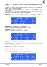
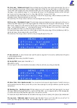
-  -  -  - O P T  I O N S - M E N U -  -  -  - 


6  ) T  o  r  q u e    s e  t  :      u n  i  t 



7  ) V e  r  s  i  o n s                   


8  ) S e  r  i  a  l    n  .  0 0 0 0 0 0 0 0 


6) Torque mode

this parameter allows to set the % or # (numerical value) operating mode of the control 

unit.  Each  time  this  parameter  is  changed,  the  unit  of  measurement  is  set  automatically  in  Nm  and  any 
compensation value is reset. If you change from % to #, an intermediate speed and torque value will be set 
for each program, while in reverse the maximum values are set. If you move from # to %, the torque values 
set for each program will be converted into a percentage.


7) Model Detect

: this function allows you to enable or disable automatic screwdriver recognition. If 

set to Auto, the unit recognizes and sets the screwdriver autonomously. In case of the screwdriver is 
not connected, the unit shows the warning "

Connect screwdriver

". When you connect a screwdriver 

different from the previous one or after formatting the unit (or on first use), the warning "

Change 

model

?" and the user can select "

No

" or "

Yes

". At the same time, the scrolling notice "

All program 

settings will be reset

" will be displayed to underline the fact that if "

Yes

" is selected, the torque, speed, 

etc. settings will be displayed. related to the previously connected screwdriver model will be lost. In 
the latter case, the new connected screwdriver will be set and the relative default values for torque 
and speed will be loaded. If the user selects "

No

" and leaves the screwdriver connected, the warning 

"

Connect  right  model

"  which  is  the  one  set  in  the  "

Model

"  function  of  the  relevant  program, 

tightening is not allowed. In this mode it is not possible to manually set a screwdriver model. If there 
is no screwdriver connected to the unit, the display shows ---- instead of the model and torque. In 
case of an unrecognizable screwdriver is connected, the unit will not show any model and tightening 
will not be allowed.  
If this function is set in 

manual

, automatic model recognition is disabled and the user will select the 

desired screwdriver model through the Program menu). After formatting the unit or its first use with 
the Model Detection setting in Manual, the warning "

Select Model

" will appear on the display.  

 
In both operating modes (Auto and Manual), if in field 3) of the Program menu you are in the “

Model

----“  status,  it  is  not  possible  to  change  the  values  relating  to  the  torque  and  speed  in  tightening 
(unscrewing).  
 
ATTENTION: with the model detection set to Auto in case of recognition malfunctions caused for 
example  by  external  interferences,  set  the  model  detection  in  Manual  and  select  the  desired 
screwdriver.  
 

IMPORTANT: the “Model Detection” function is active only in the  inline models PLUTO3, 
PLUTO6, PLUTO10, PLUTO15. 


8) Versions: 

in this screen you can see the versions of boards mounted inside the unit.


9) Serial number: 

it is the indication number of the control unit. Default number: 0000000. 

It could be the real serial number of the unit or another one you could choose (7 digits max). 
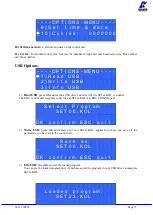
This number will also be the name of the folder in the USB drive where you will save the report of your data 
(see EDU EXPAND part). 
 

Summary of Contents for 034000/TOP/TA

Page 1: ...ONFORMITY KOLVER S r l declares that the new tool here described control unit model EDU2AE TOP TA is in conformity with the following standards and other normative documents 2006 42 CE LVD 2014 35 UE...

Page 2: ...through a percentage the tightening and unscrewing torque values are set directly as the desired value and in the selected unit of measurement Torque setting Model Torque Nm Speed rpm Unit Min Max MI...

Page 3: ...ESC key for 2 seconds Select the line by pressing or then press OK the symbol will turn into Press the or to select the required value and then confirm through OK or ESC if you don t want to save the...

Page 4: ...it the buttons the unit mode date and time the firmware version the serial number and the cycles done USB Options It indicates the menu section where you can view upload and create programs setting of...

Page 5: ...ired torque as a percentage of the torque range of the selected screwdriver For example for a Pluto10 a 50 setting will result in a torque in the area of 4 5 Nm The torque range is always referred to...

Page 6: ...ed Time is ON 9 Final Spd Final Speed You can select any speed value of the screwdriver between nominal maximum speed given in the catalogue and the minimum speed of every single screwdriver see table...

Page 7: ...crewdriver between the maximum and the minimum specific speed of every single screwdriver see table with technical data In Unit mode even the reverse speed is linked to the relative table of the screw...

Page 8: ...K when ON press OK at the end of each program When OFF the control unit resets automatically at the end of each program 20 Press ESC when ON press ESC to reset the control unit When OFF the control un...

Page 9: ...set the highest value of the torque range When Calibration is OFF the maximum torque value automatically sets on 55 Nm The selection of the torque value is carried out by entering the digit cell by ce...

Page 10: ...ed S E QU E NC E ME N U 3 E x t b o x o f f 4 M o d b a r c o f f 5 I n s b a r c o d e S e q 3 Ext box It allows to enable or disable the external control IMPORTANT It is mandatory to select ON to wo...

Page 11: ...t Options OP T I O N S ME N U OK c h a n g e E S C q u i t 1 L a n g u a g e E N 2 C h a n g e p a s s w o r d 1 Language This option allows to choose among the languages available English French Germ...

Page 12: ...nected screwdriver will be set and the relative default values for torque and speed will be loaded If the user selects No and leaves the screwdriver connected the warning Connect right model which is...

Page 13: ...e USB drive and select the file SETxx KOL you desire The EDU control unit recognizes only files as SETxx KOL see EDU EXPAND part S e l e c t P r o g r a m S E T 0 0 KOL OK c o n f i r m E S C q u i t...

Page 14: ...wing screen will appear on the display ME N U 2 3 C a l i b r a t i o n o n 3 Press OK to confirm If you choose OFF calibration will be interrupted and no torque value will be displayed You choose ON...

Page 15: ...bration values will be referred to the parameters of the control unit which are set during calibration i e if you modify speed or torque the unit will need to be recalibrated During calibration when a...

Page 16: ...w is correctly tightened If the torque and or angle are outside the preset values the screw will be considered as incorrectly tightened In this case the red led will light up and the message Error Max...

Page 17: ...n led will light up and the message tightening OK will be displayed on the status bar If the screwdriver stops before reaching the preset angle the tightening will be considered not ok the red led wil...

Page 18: ...0 5 1 9 2 500 0 5 1 0 4 5 8 9 5 1 10 2 550 0 6 1 1 5 4 9 7 6 2 11 2 600 0 7 1 2 6 2 10 6 7 2 12 2 650 0 7 1 3 6 2 11 5 7 2 13 3 700 0 8 1 4 7 1 12 4 8 2 14 3 800 0 9 1 5 8 0 13 3 9 2 15 3 850 PLUTO 3...

Page 19: ...2 5 11 6 22 1 13 3 25 5 60 1 5 4 5 13 3 39 8 15 3 45 9 80 2 0 6 1 17 8 54 0 20 4 62 2 100 2 1 7 7 18 6 68 2 21 5 78 5 130 2 2 9 8 19 5 86 7 22 5 99 9 170 2 3 11 4 20 4 100 9 23 5 116 2 210 2 4 12 7 2...

Page 20: ...X min MAX rpm 4 2 14 0 37 2 123 9 42 9 142 8 20 7 4 25 1 65 5 222 2 75 5 255 9 30 8 4 33 6 74 4 297 4 85 7 342 6 40 8 9 39 3 78 8 347 8 90 8 400 7 50 9 4 43 2 83 2 382 4 95 9 440 5 60 9 5 45 6 84 1 40...

Page 21: ...3 3 52 0 600 1 4 5 5 12 4 48 7 14 3 56 1 700 1 5 5 9 13 3 52 2 15 3 60 2 800 1 7 6 1 15 1 54 0 17 4 62 2 850 PLUTO 8 ANG Nm Lbf in Kgf cm min MAX min MAX min MAX rpm 1 0 1 7 8 9 15 0 10 2 17 3 110 1 2...

Page 22: ...connectors allow to enable functions through inputs and to take signals through outputs The inputs are activated by connecting them to ground A positive voltage must NEVER be brought to these inputs B...

Page 23: ...Vers 100822 Page 23 to protection displaying the message output disable To restore the outputs after a protection turn off and turn on the unit again...

Page 24: ...ing screwing Signal is 24V 5 SCREW OK Correct screw signal The green led on the front panel will switch on Signal is 24V INPUT 6 T A INPUT External input for making the control unit start to count the...

Page 25: ...nu remote OK key function 4 ESC EXT If enabled see point 4 OK ESC in the option menu ESC key function to reset remote errors 5 RESET EXT If enabled see point 4 OK ESC commands in the option menu it re...

Page 26: ...nal works in parallel with the yellow led on the front panel 4 SEQUENCE END It indicates the end of a sequence if enabled 5 NOK T A It activates if any angle error occurs 6 PR OK It activates at the e...

Page 27: ...UTPUT 3 It indicates you re using program 3 4 OUTPUT 4 It indicates you re using program 4 5 OUTPUT 5 It indicates you re using program 5 6 OUTPUT 6 It indicates you re using program 6 7 OUTPUT 7 It i...

Page 28: ...point 4 OK ESC in the option menu ESC key function to reset remote errors 16 RESET EXT If enabled see point 4 OK ESC in the option menu it resets program or sequence according to the preset function...

Page 29: ...rcuit will result in the stop of the unit To re activate signals it is necessary to switch off the unit for 5 6 seconds check connections and output loads then switch the unit on CORRECT SCREWS MESSAG...

Page 30: ...yed on the status bar the lever has been released before the runtime has been achieved 5 Under min time is displayed on the status bar the torque signal is displayed below the pre set minimum time 6 O...

Page 31: ...led or disabled through PROGRAM MENU see point 18 on the program menu 18 Reverse torque error is displayed on the status bar The torque signal is displayed while loosening but only if it s set on max...

Page 32: ...t or incorrect OK the torque has been correctly reached all the selected parameters are satisfied and the control unit will give out a beep sound of 0 5 sec NOK the torque has been reached during ramp...

Page 33: ...e to use EDU EXPAND Double click the icon program and this is the main view New program to load a new program Load from file it loads all programs sequences and option settings from a previously saved...

Page 34: ...rive and upload to the unit or recall with EDU EXPAND Upload to unit it uploads all the setting to the EDU control unit Connect the unit to your computer through miniUSB or RS232 Switch the unit on Cl...

Page 35: ...connect the USB drive to the control unit the unit creates a folder where the report of the screwing done will be saved The folder is named as the serial number of the unit The text file which contai...

Page 36: ...Vers 100822 Page 36 EXPLODED VIEW EDU2AE TOP TA 6 00...

Page 37: ...TA 1 819006 14 USB Flat cable 1 872474 15 USB Device 1 852424 16 USB Pen drive 1 872475 17 M12 8pin nut ferrite connector 1 201766 LTA 18 M3 Washer h0 5 mm 4 800042 19 Spacer 15mm dest 4 8 mm 4 890004...

Page 38: ...e free of charge such items 3 This guarantee does not cover repair or replacement required as a consequence of products which have been abused misused or modified or which have been repaired using not...

Reviews: