4. Check the AKD PDMM address setting and make sure that S1 is set to a nonzero
value (static IP connection).
The connection is now configured to establish a point-to-point direct connection be
-
tween the AKD PDMM and the PC using the KAS IDE. You can now skip to Step 8.
Option B: Network device connection
1. Set the rotary switch on the AKD PDMM to zero.
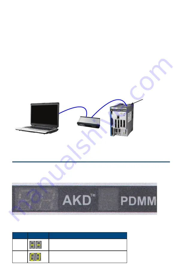
2. Connect the AKD PDMM and the PC to the network. The network must include a
DHCP server (usually standard in corporate networks). If the network does not have
a DHCP server, you can connect using a stand-alone router with a built-in DHCP
server.
In either case, both the PC and the AKD PDMM acquire IP addresses auto
matically.
Figure 16. Option B: Connection to a Router
Step 8: Confirm Connections
After completing Steps 1 through 7, you can turn on logic power to the AKD PDMM
through the
X1
connector (bus voltage is not needed for communications). The AKD
PDMM has two LED displays:
Figure 17. LED Displays
Left Display (Drive LED)
Step
Display
Description
1
Power on
2
13
PC Running KAS IDE
Router
AKD PDMM
X32 Connection
AKD PDMM Quick Start | Connect AKD PDMM Communication


