background image

AUTO PICLE-S

33

7

Troubleshooting

Repairs are only to be conducted by a qualified professional.

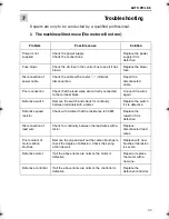
1 The machine will not move (The motor will not run)

Problem

Possible cause

Solution

Power is not 
supplied

Check the power supply.
Check the connections.

Replace the power 
supply if it is 
defective.

Fuse blown

Check the 2A fuse in the control box to see if it has 
blown.

Replace the blown 
fuse.

Disconnection of 
power cable

Check the cable with a tester. “

y

” indicates 

disconnection.

Repair the 
disconnected 
cable.

Poor connection

Check that the lead wires are correctly connected 
to the terminal block.

Connect the wires 
again.

Defective switch

Remove the switch and check for continuity 
between terminals with a tester.

Replace the switch 
if it is defective.

Defective speed 
resistor

Check with a tester that the resistance is 50 k

q

.

Replace the 
resistor if it is 
defective.

Disconnection of 
lead wire

Check for continuity between the lead wires with a 
tester.

Replace 
disconnected lead 
wires.

Poor contact of 
motor carbon 
brushes

Remove the cap and pull out the carbon brushes to 
check the degree of abrasion. Check the spring 
action as well.

Replace with new 
brushes if abrasion 
is severe.

Defective motor

If all the above items are normal, the motor is 
defective.

Repair or replace 
the motor with a 
new one.

Defective controller

If all the above items are normal, the controller is 
defective.

Replace the 
defective controller.

Auto Picle-S.book  Page 33  Thursday, April 11, 2002  11:15 AM

Summary of Contents for AUTO PICLE-S

Page 1: ...AUTO PICLE S REMOTE CONTROL GAS MOTORIZED PIPE CUTTING MACHINE KOIKE SANSO KOGYO CO LTD...

Page 2: ...of machine 13 3 1 Features of machine 13 3 2 Name and function of each section 14 3 3 Specifications 15 4 Preparation for operation 17 4 1 Contents of package 17 4 2 Machine assembly 18 4 3 Preparati...

Page 3: ...ic parts 31 6 1 2 Disassembly for maintenance and inspection of the gear case 32 6 2 Daily inspection 32 6 3 3 Month or 1000 hour inspection 32 6 4 6 Month inspection 32 7 Troubleshooting 33 8Wiring d...

Page 4: ...maintains the machine can refer to it if necessary Do not use the machine carelessly without following the instructions in the manual Use the machine only after you completely understood the contents...

Page 5: ...aught Possible injury to fingers if caught in the insertion point Caution Electric shock Possible electric shock under special conditions Ground this equipment Operators must ground the equipment usin...

Page 6: ...rning Indicates a potentially hazardous situation which if not avoided could result in death or serious injury The safety label on the machine is positioned at places that could cause injury or seriou...

Page 7: ...achine before operation The input power voltage should be in the range of 10 of the rated voltage The machine should not be operated out of this range 2 The metal plugs are screw threaded therefore fu...

Page 8: ...with oil or grease 1 3 3 High pressure gas cylinder safety precautions 1 Never use broken cylinders or cylinders from which gas is leaking 2 Install cylinders upright and take measures to prevent them...

Page 9: ...e sparks 2 Do not cut containers filled with flammables 3 Do not keep lighters matches and other flammables nearby 4 Flames from the torch will burn the skin Keep your body away from the torch and tip...

Page 10: ...se knocking will result 7 Weak chain tension will make the machine slip Give an appropriate tension to the chain 8 Be careful not to get your hand caught between the upper plate and the slide brackets...

Page 11: ...AUTO PICLE S 10...

Page 12: ...Safety labels and other labels for correct operation are affixed to the machine Carefully read the labels and follow the instructions on them when operating the machine Never remove the labels Keep th...

Page 13: ...AUTO PICLE S 12...

Page 14: ...cutter developed on the basis of the through going examination of the actual conditions of pipeline installation work sites The machine will exhibit excellent performance in straight and bevel cutting...

Page 15: ...the torch Two hoses for oxygen and gas are combined as a set 8 Motor switch Power switch for the motor 9 Tightening handle Tightens the handle to secure the machine and pipes 10 Gas distributor Divisi...

Page 16: ...ckness 50 mm Bevel angle 0 45 Tip 102 HC for acetylene 106 HC for propane 0 1 2 Gas oxygen acetylene gas or LPG gas Pipe cutting diameter 150 400 mm without guide rail 400 1500 mm with guide rail Acce...

Page 17: ...AUTO PICLE S 16 Option Guide rail pipe cutting diameter D 600 400 600 D 900 600 900 D 1200 900 1200 D 1500 1200 1500...

Page 18: ...plete The following is a list of the parts you should receive Body 1 set Gas distributor 1 set Torch holder 1 set Torch 1 pc Hose Distribution hose 3 pcs set 900L 1 set Slide bar 1 pc Control box 1 se...

Page 19: ...pper back to their positions in this order 4 Insert the slide bar into the slide cover and cross feed bar 5 Tighten the wing bolts M4x10 and M4x15 4 3 Preparation for operation 4 3 1 Connecting the po...

Page 20: ...the primary hose 2 Securely tighten the joints 3 Check that there is no gas leakage 4 3 3 Connecting the tip Warning Avoid damaging the taper of the tip since this may cause backfire 1 Select a proper...

Page 21: ...se and fix the main unit to the pipe When turning the tightening handle exercise care so that the spring will not be in close contact leaving a clearance of 1 2 mm 5 To avoid a chain engagement error...

Page 22: ...e rail 1 Assembling the rail a Attach the supporting bases set at intervals of 120 mm to the guide rail that matches the pipe diameter b Change the number of supporting bases set taking into considera...

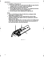
Page 23: ...g tightened d Secure the guide rail by tightening the adjusting nut Note Take care that the hand clamp 3 will not be unclamped while tightening the adjusting nut 1 Tighten the adjusting nut to the ext...

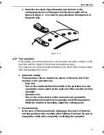
Page 24: ...e clutch Automatic turning Final operation can be checked by means of the main unit of the machine or the operation box Main unit Turn on the rotational direction switch in the operation box and opera...

Page 25: ...AUTO PICLE S 24...

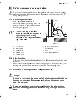
Page 26: ...eferring to the Cutting Data select the suitable tip according to the plate thickness For a heavily rusted plate or a bevel cutting angle of more than 20 select the tip one grade higher than the one s...

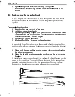
Page 27: ...and about 5 6 mm in length 4 Open the jet oxygen valve fully 5 Readjust the flame if its condition has changed A disorderly flow of the jet oxygen will adversely affect the quality of the cutting surf...

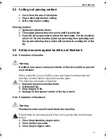
Page 28: ...ainst backfire and flashback 5 4 1 Prevention of backfire Warning Backfires may cause serious accidents or fires Be careful to prevent such disaster When a backfire occurs find the cause and inspect a...

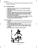
Page 29: ...he cutting condition select the optimal cutting speed with the speed adjuster 5 After cutting turn off the switch and close the cutting oxygen valve fuel gas valve and preheating oxygen vale in this o...

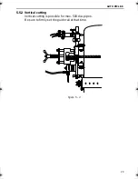
Page 30: ...AUTO PICLE S 29 5 5 2 Vertical cutting Vertical cutting is possible for max 500 dia pipes Be sure to firmly set the guide rail at that time figure 5 4...

Page 31: ...AUTO PICLE S 30...

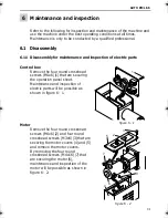
Page 32: ...ox Remove the four round crosshead screws M4x6 1 that are securing the operation panel sheet Maintenance and inspection of electric parts will be possible as shown in figure 6 1 Motor Remove the four...

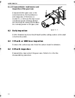
Page 33: ...s M6x16 8 that are securing the casing 9 and apply the notemp grease to the gear case 6 2 Daily inspection Oil the threaded section of the lift shaft and the sliding section of the shaft column every...

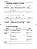
Page 34: ...ires again Defective switch Remove the switch and check for continuity between terminals with a tester Replace the switch if it is defective Defective speed resistor Check with a tester that the resis...

Page 35: ...cause Solution Malfunction Remove the speed reducer box to check the clutch operation Disassemble and clean Idle rotation of reduction gear The reduction gear is rotating idly when the motor keeps run...

Page 36: ...ce or repair Hoses or cabtyre cords hinder smooth running Pay attention during operation Flaws on the drive and the drive wheel or adhesion of foreign material Replace or repair The chain tension is i...

Page 37: ...AUTO PICLE S 36...

Page 38: ...itch 4 Resistor 10q 7W 5 0 75 mm Cabtyre cord 5m 6 Control box 7 SW2 switch 8 Scr control 9 Variable resistor 50kq B 1 4W 10 F Fuse 2A 11 SW1 Switch Power 12 AG cable 13 Terminal block 5 1 6 3 9 11 12...

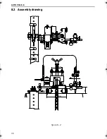
Page 39: ...AUTO PICLE S 38 8 2 Assembly drawing figure 8 2...

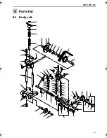
Page 40: ...AUTO PICLE S 39 9 Parts list 9 1 Body unit...

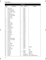
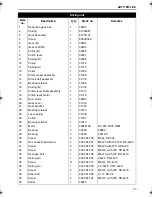
Page 41: ...1 31334 16 Drive gear 1 31333 17 Sprocket shaft 1 31334 18 Collar A 1 31338 19 Collar B 1 31336 20 Collar C 1 31337 21 Slide shaft 2 31340 22 Lift shaft 1 31341 23 Upper plate 1 31342 24 Spring 1 313...

Page 42: ...685 M4x10 BS 4x10 47 Wing bolt 1 222 004 686 M4x15 BS 4x15 48 Screw 2 222 004 227 M4x10 with SW BC 4x10 49 Wing bolt 1 222 004 686 M8x15 BS 8x15 50 Nut 5 222 004 404 M6 With WF NH 6 51 Screw 1 222 004...

Page 43: ...AUTO PICLE S 42 9 2 Driving unit...

Page 44: ...over 1 31319 21 Gear bracket 1 31320 22 Bearing retainer 1 31279 23 Lever spring 1 31236 24 Clutch 1 31307 25 Bearing retainer 1 31014 26 Motor 1 69000126 DC 24V 5000 RPM 27 Bearing 2 30269 608ZZ 28 B...

Page 45: ...AUTO PICLE S 44 Description Q ty Stock no Remarks 41 No 2 worm assembly 1 32469 Double thread 42 Carbon cap 2 33365 43 Carbon brush 2 30752 Driving unit...

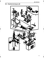
Page 46: ...AUTO PICLE S 45 9 3 Electrical and gas unit...

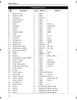
Page 47: ...ocket 1 61001377 6P x 25 19 Cap for dust protector 3 32431 20 Switch 1 30822 S 332 21 Fuse 1 6N191010 1A 22 Resistor 1 31247 RGB 7 10q 7W 23 Name plate for switch ON OFF 1 32433 24 Hose for oxygen 1 3...

Page 48: ...374 WP 1 42 Spacer 2 36049 SP 5 43 Srew 2 222 004 702 M3x5 44 Screw 2 222 004 702 M3x5 45 Controller 1 69000105 46 Nut 1 M4 47 Transformer 1 6100472 For 100 220V Transformer 1 6100672 For 230 240V Tra...

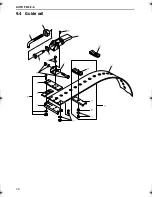
Page 49: ...AUTO PICLE S 48 9 4 Guide rail...

Page 50: ...ate B 32443 Decide Q ty according to the length of rail 11 Sub base 32444 12 Spring plate for sub base 32444 13 Guide rail D 1500 1 32446 4974 mm Guide rail D 1200 32457 4014 mm Guide rail D 900 32458...

Page 51: ...AUTO PICLE S 50...
Page 52: ...a Plate thickness Tip size Cutting speed Oxygen pressure kg cm2 Fuel gas pressure Kerf width mm mm min Cutting Preheat kg cm2 mm 3 00 680 1 5 1 5 0 2 1 6 0 610 2 2 0 2 1 3 10 0 560 2 2 0 2 1 5 12 5 1...

Page 53: ...e thickness Tip size Cutting speed Oxygen pressure kg cm2 Fuel gas pressure Kerf width mm mm min Cutting Preheat kg cm2 mm 3 00 680 1 5 1 5 0 2 1 6 0 610 2 2 0 2 1 3 10 0 560 2 2 0 2 1 5 12 5 1 530 2...

Page 54: ...otor 15W 10 000 rpm Note The machine unit and the guide rail are sold separately Please order the machine and the required rail in one set The machine unit is composed of the machine body and chain of...

Reviews: