


TP-6198 3/15
60 Section 5 Component Testing and Adjustment
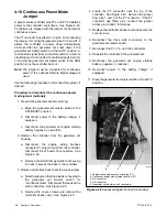
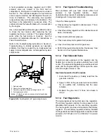
Checking Fuel Pressure
Use a gauge or manometer to check the fuel pressure at
the secondary regulator inlet.
See Figure 5-16.
Measure the fuel pressure with the generator set
running at rated load. The fuel pressure should be
178--280 mm (7--11 in.) water column or 1.7--2.7 kPa
(4--6 oz./in.
2
). Contact the fuel supplier if the inlet
pressure is not within the specified range.
5.11.4 Fuel Conversion
The fuel system can be converted from natural gas to LP
vapor (or vice-versa) in the field. See the generator set
Installation Manual for fuel system conversion and fuel
mixture adjustment procedures.
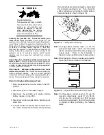
5.12 Fuses
Three fuses protect the controller, SCR module, and
relay interface board.
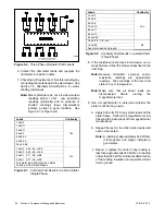
See Figure 5-17 for fuse
locations. See Figure 5-18 for fuse ratings and part
numbers.
Always identify and correct the cause of a blown fuse
before restarting the generator set. Refer to Section 3,
Troubleshooting, for conditions that may indicate a
blown fuse.
Replace blown fuses with identical
replacement parts.
1
tp6198
1. Fuses
Note:
Some earlier models had inline fuses
located in the engine harness.
Figure 5-17
Fuse Location
Fuse
Label
Part
Number
Location *
Auxiliary Winding,
10 amps
F1
358337
Lead 55
Relay Interface
Board, 10 amps
F2
223316
Lead PF2
Controller, 10 amps
F3
223316
Lead PF3
*
In engine harness on earlier models
Figure 5-18
Fuses
Summary of Contents for 15/30RES
Page 2: ......
Page 18: ...TP 6198 3 15 18 Section 1 Specifications Notes ...
Page 62: ...TP 6198 3 15 62 Section 5 Component Testing and Adjustment Notes ...
Page 71: ......


