


TP-6198 3/15
48 Section 4 Controller
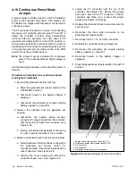
4.10 Continuous Power Mode
Jumper
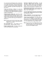
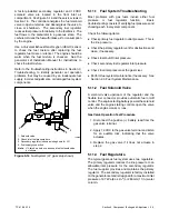
A jumper across controller pins P7-1 and P7-2 maintains
power to the controller at all times. See Figure 4-20.
Controllers are shipped with the jumper connected for
continuous power.
The P7 connector has either 2 or 3 pins. Disconnecting
the jumper or moving the jumper to pins P7-2 and P7-3
allows the controller to power down automatically
48 hours after the generator set shuts down if the
generator set master switch is in the AUTO position. A
remote start signal (from a transfer switch or a remote
start/stop switch connected to controller leads 3 and 4)
or moving the generator set master switch to the RUN
position turns the controller back on.
Note:
The jumper must be connected for continuous
power if the optional Remote Digital Gauge is
used.
Use the following procedure to disconnect the jumper, if
desired.
Procedure to disconnect the continuous power
mode jumper (optional).
1. Prevent the generator set from starting.
a. Move the generator set master switch to the
OFF/RESET position.
b. Disconnect power to the battery charger, if
equipped.
c. Disconnect the generator set engine starting
battery, negative (--) lead first.
2. Remove the controller from the generator set
housing.
a. Disconnect the engine wiring harness
connector P1 plug (35-pin) from the controller.
Disconnect the J15 and J16 connectors. See
Figure 4-20.
b. Remove controller from generator set housing
in order to access the back of the controller.
3. Remove controller’s back cover to access jumper.
a. Note the labels on the three leads connected to
the
generator
set
master
switch
for
reconnection later. Disconnect the leads at the
pink connectors. See Figure 4-20.
b. Remove the cover screws and remove the
controller’s back cover. See Figure 4-20.
4. Locate the P7 connector near the top of the
controller. See Figure 4-20. Remove the jumper
from pins 1 and 2 of the P7 connector. If the P7
connector has three pins, connect the jumper
across pins 2 and 3 for storage.
5. Replace the controller’s back cover and secure the
cover screws.
6. Reconnect the three pink connectors to the
generator set master switch.
7. Reconnect the P1, J15, and J16 connectors.
8. Reinstall the controller in the generator set.
9. Reconnect the generator set engine starting
battery, negative (--) lead last.
10. Reconnect power to the battery charger, if
equipped.
11. Place the generator set master switch in the AUTO
position.
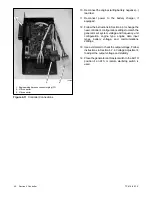
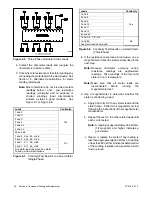
1. Engine wiring harness connector plug (P1)
2. Continuous power mode jumper location (P7)
3. J15 connector
4. J16 connector
5. Generator set master switch connectors
tp6195
1
5
3
4
2
Figure 4-20
Advanced Digital Control Connections
Summary of Contents for 15/30RES
Page 2: ......
Page 18: ...TP 6198 3 15 18 Section 1 Specifications Notes ...
Page 62: ...TP 6198 3 15 62 Section 5 Component Testing and Adjustment Notes ...
Page 71: ......


