


TP-6198 3/15
27
Section 3 Troubleshooting
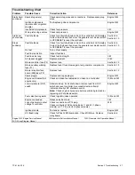
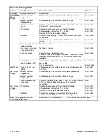
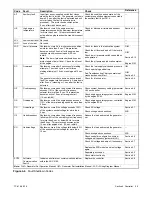
Troubleshooting Chart
Problem
Reference
Corrective Action
Possible Cause
Starts hard,
continued
Spark plug wire(s)
Check spark plug wires and connections. Replace spark plug
wires.
Engine S/M
Ignition components
(spark control or ignition
module)
Test/replace ignition components.
Engine S/M
Insufficient fuel pressure
Check fuel pressure
I/M
Worn piston rings, valves
Check compression.
Engine S/M
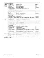
Starts but
shuts down
Fault shutdown
Check for a fault shutdown code on the controller’s LED display.
Correct the fault and then move the generator set master switch
to OFF/RESET to reset the controller.
Section 4.5
Section 5.10
Stops
suddenly
Fault shutdown
Check for a fault shutdown code on the controller’s LED display.
Correct the fault and then move the generator set master switch
to OFF/RESET to reset the controller.
Section 4.5
Section 5.10
No fuel
Turn on fuel supply.
—
Fuel line restriction
Inspect fuel lines.
—
Fuel lines too long
Check fuel line length.
I/M
Air cleaner clogged
Replace element.
O/M
Blown controller fuse (F3) Replace fuse.
Section 5.12
Blown auxiliary winding
fuse (F1)
Replace fuse. If fuse blows again, test generator components.
Section 5.12
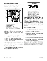
Blown relay interface
board (RIB) fuse (F2)
Replace fuse.
Section 5.12
Spark plug(s)
Replace and regap plug(s).
Engine S/M
Engine overheated (hot
engine only)
Check air intake, fuel adjustment, oil level, air inlet/outlet.
O/M and I/M
Low oil pressure (LOP)
switch
Attempt startup. If unit shuts down, remove lead from LOP
switch and reset controller. A successful restart attempt
indicates a faulty LOP shutdown switch.
Note:
Check engine oil pressure before performing test and/or
replacing LOP shutdown switch.
Engine S/M
Fuel valve/fuel regulator
Check regulator/valve operation.
O/M and I/M
Engine overloaded
Reduce electrical load.
I/M
Loss of generator output
voltage to controller
Check connections at P15 plug.
Check continuity of AC sensing leads 11 and 44 (1-phase
models) or V7, V8, and V9 (3-phase models).
W/D
Ignition module
Test and/or replace.
Engine S/M
K3 (flash) relay
Check for Flash LED illumination. Check RIB fuse. Replace
relay board.
Section 4.6
Engine S/M: Engine Service Manual
I/M: Generator Set Installation Manual
O/M: Generator Set Operation Manual
W/D: Wiring Diagram Manual
Summary of Contents for 15/30RES
Page 2: ......
Page 18: ...TP 6198 3 15 18 Section 1 Specifications Notes ...
Page 62: ...TP 6198 3 15 62 Section 5 Component Testing and Adjustment Notes ...
Page 71: ......


