

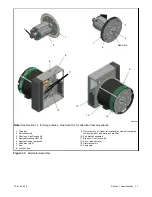


TP-6198 3/15
29
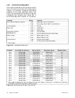
Section 3 Troubleshooting
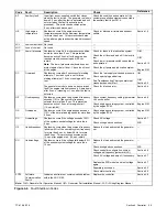
Troubleshooting Chart
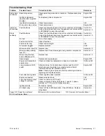
Problem
Reference
Corrective Action
Possible Cause
Low output
or excessive
drop in
voltage
Generator overloaded
Reduce load.
—
Incorrect controller
configuration
Check and adjust the controller configuration parameters.
Section 4.9.2
Incorrect controller
voltage settings
Check and adjust the controller voltage settings.
Section 4.9.2
Alternator or control
system
Perform separate excitation procedure to isolate problem to the
alternator or the control system.
Section 5.2
SCR module
Check wiring and connections to the SCR module.
Check auxiliary winding fuse F1 (lead 55).
Replace SCR module and test voltage.
Section 5.12
Section 4.7
Controller
Check controller settings. Check controller fuse, wiring and
connections.
Before replacing controller, replace SCR module and test
voltage.
Section 4.9.2
Section 4.8
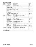
Rotor (open, grounded, or
shorted windings)
Test and/or replace.
Section 5.4
Stator (open, grounded,
or shorted windings)
Test and/or replace.
Section 5.3
Brush connection
Check for loose brush connections.
Check the resistance through the brushes. Resistance through
the brushes should be low, 0.1--0.2 ohms without meter lead
resistance.
Section 5.6
Low engine speed
causing voltage roll-off
Check system voltage/frequency (Uu) and engine type (Ec)
parameters
Troubleshoot engine
Section 4.9.2
Engine S/M
Light flicker
Voltage stability (gain)
setting
Check and adjust the voltage stability (gain) setting using the
ADC 2100.
Section 5.7
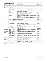
High output
voltage
Incorrect controller
configuration
Check and adjust the controller configuration parameters.
Section 4.9.2
Incorrect controller
voltage settings
Check and adjust the controller voltage settings.
Section 5.7
Loose voltage sensing
connections
Check connections: stator leads 11 and 44 (1-phase models) or
V7, V8, and V9 (3-phase models) and P15 controller
connection.
W/D
High output
voltage,
continued
SCR module
Check wiring and connections to the SCR module.
Check auxiliary winding fuse F1 (lead 55).
Replace SCR module and recheck voltage.
Section 4.7
Section 5.12
Section 4.7
Controller
Check fuses, wiring and connections. Before replacing
controller, replace SCR module and test voltage.
Section 4.8
Engine S/M: Engine Service Manual
I/M: Generator Set Installation Manual
O/M: Generator Set Operation Manual
W/D: Wiring Diagram Manual
Summary of Contents for 15/30RES
Page 2: ......
Page 18: ...TP 6198 3 15 18 Section 1 Specifications Notes ...
Page 62: ...TP 6198 3 15 62 Section 5 Component Testing and Adjustment Notes ...
Page 71: ......


