


TP-6198 3/15
31
Section 4 Controller
Section 4 Controller
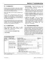
4.1 Introduction
This section describes the operation and replacement of
the ADC 2100 controller. Controller configuration and
adjustment are explained in Section 4.9. See Section 3
for troubleshooting procedures.
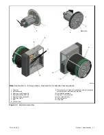
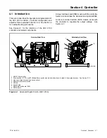
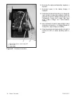
See Figure 4-1 for the locations of the ADC 2100
controller and related components.
A relay interface board (RIB) is used with the controller.
Section 4.6 describes the standard and optional RIBs.
A silicon controlled rectifier (SCR) module works with
the controller to regulate the output voltage. See
Section 4.7.
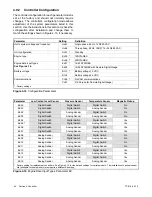
GM32850B-
1. ADC 2100 controller
2. Fuse location (F1, F2, and F3)
Note:
Some earlier models had inline fuses located in the engine harness. See Section 5.12.
3. Line circuit breaker panel (load connection)
4. Generator set master switch
5. L0 stud
6. Ground stud
7. Relay interface board (RIB)
8. SCR module
Service-Side View
Alternator-End View
1
2
3
4
5
6
7
8
Figure 4-1
Advanced Digital Control (ADC 2100)
Summary of Contents for 15/30RES
Page 2: ......
Page 18: ...TP 6198 3 15 18 Section 1 Specifications Notes ...
Page 62: ...TP 6198 3 15 62 Section 5 Component Testing and Adjustment Notes ...
Page 71: ......


