


TP-6198 3/15
59
Section 5 Component Testing and Adjustment
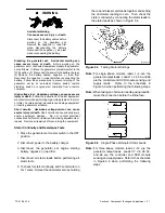
A factory-installed secondary regulator and 12 VDC
solenoid valve are located in the front inlet air
compartment. See Figure 5-16 and the service views in
Section 1.6. The controller energizes the fuel solenoid
valve to open at startup and deenergizes the valve to
close at shutdown.
The secondary fuel regulator
reduces fuel pressure for delivery to the fuel block. The
fuel flows to the carburetor in a gaseous state. The
carburetor mixes the fuel with intake air for consumption
by the engine.
Use a Universal Exhaust Gas Oxygen (UEGO) sensor
to check the fuel mixture after replacing the fuel
regulator, fuel mixer, or silencer. The engine should be
warm when the fuel mixture is checked. See the
generator set Installation Manual for instructions to
check the fuel mixture.
Refer to the troubleshooting instructions in Section 3,
Troubleshooting, to identify generator set operation
problems that may be caused by an inadequate fuel
supply, incorrect adjustments, or damaged fuel system
components.
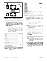
1
tp6329
1. Solenoid valve
2. Check inlet fuel pressure here
3. Secondary regulator (shown pointing down for LP)
4. Fuel supply connection
3
4
2
Note:
UL-listed models use a second fuel solenoid valve,
not shown.
Figure 5-16
Fuel System (LP gas setup shown)
5.11.1 Fuel System Troubleshooting
Most problems with gas fuels involve either fuel
pressure
or
fuel
regulator
function.
Basic
troubleshooting consists of verifying fuel pressures and
checking each fuel system component.
Check the following items:
D
Check primary fuel regulator outlet pressure. This is
the line pressure.
D
Check the primary regulator vent for obstructions and
clean, if necessary.
D
Check fuel shutoff inlet pressure.
D
Check secondary fuel regulator inlet pressure.
D
Check fuel inlet pressure at the gas mixer.
D
Perform fuel system maintenance if necessary. See
Section 2.3, Fuel System Maintenance.
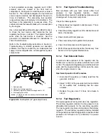
5.11.2 Fuel Solenoid Valve
A solenoid valve upstream of the regulator and the
flexible fuel connector provides automatic fuel on/off
control. The engine starting battery powers the solenoid
valve and the engine starting controls open the valve
when the engine cranks or runs.
Gas Valve Operation Test Procedure
1. Disconnect the positive (+) battery lead from the
gas valve terminal.
2. Apply 12 VDC to the gas valve terminal and listen
for an audible click, indicating that the valve
actuates.
3. Replace the gas valve if it does not actuate in
step 2.
5.11.3 Fuel Regulators
The typical gaseous fuel system uses two regulators.
The primary regulator reduces the line pressure to an
allowable inlet pressure for the secondary regulator.
The fuel supplier provides and maintains the primary
regulator. The secondary regulator is factory-installed
on the generator set and is designed for a maximum inlet
pressure of 2.7 kPa (6 oz./in.
2
) or 280 mm (11 in.) water
column.
Summary of Contents for 15/30RES
Page 2: ......
Page 18: ...TP 6198 3 15 18 Section 1 Specifications Notes ...
Page 62: ...TP 6198 3 15 62 Section 5 Component Testing and Adjustment Notes ...
Page 71: ......


