background image

2-2

A-61698  November  2010 

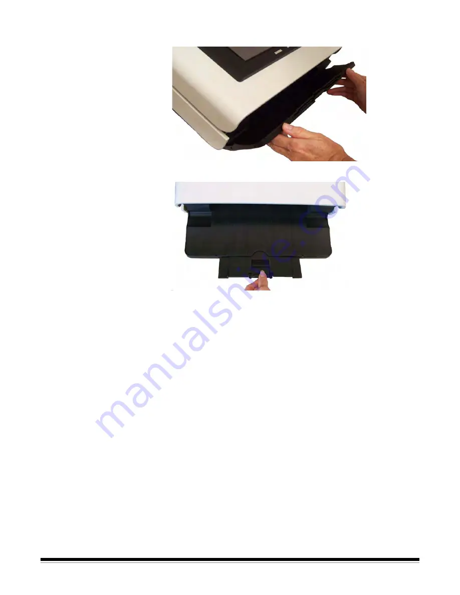
3. Be sure the output tray panel is down. 

4. Adjust the output tray by pulling out the extender if needed.

Getting your 
documents ready

1. Standard paper size documents feed easily through the Scan 

Station. When organizing your documents for scanning, stack the 
documents so the lead edges are aligned and centered in the input 
tray. This allows the feeder to introduce documents into the Scan 
Station one at a time.

2. Remove all staples and paper clips before scanning. Staples and 

paper clips on documents may damage the Scan Station and 
documents.

3. All inks and correction fluids on the paper must be dry before 

scanning is started. 

Summary of Contents for Scan station Pro 550

Page 1: ......

Page 2: ...INTRODUCTION 1 1 USING THE SCAN STATION 2 1 MAINTENANCE 3 1 TROUBLESHOOTING 4 1 APPENDICES A B...

Page 3: ...ing procedures Do not use air liquid or gas spray cleaners These cleaners displace dust dirt and debris to other locations within the scanner which may cause the Scan Station to malfunction Material S...

Page 4: ...roduct may cause radio interference in which case the user may be required to take adequate measures Japan This is a Class A product based on the standard of the Voluntary Control Council for interfer...

Page 5: ...es to communicate with other network devices or destinations The color touch screen is easy to use and allows you to quickly send your documents via a predefined job setup with a simple touch Supporti...

Page 6: ...scanning documents Output tray extender pull this extender out when scanning documents longer than 11 inches 28 cm Output tray panel covers the transport when not in use When opened collects the scan...

Page 7: ...on module and rollers provides smooth document feeding and separation of various sizes thicknesses and textures of documents Imaging guides for optimum image quality keep the imaging guides clean Ther...

Page 8: ...ports connects peripheral devices i e keyboard mouse and other accessories to the Scan Station Security lock port connects a security lock to the Scan Station You can purchase a standard security loc...

Page 9: ...an Station 2 7 Before first use your Kodak Scan Station Pro 550 must be configured Your reseller or system administrator will need to create and load the configuration Getting your Scan Station ready...

Page 10: ...n When organizing your documents for scanning stack the documents so the lead edges are aligned and centered in the input tray This allows the feeder to introduce documents into the Scan Station one a...

Page 11: ...serted into the input tray first see below Two sided documents are scanned in one pass NOTES Depending on how your Scan Station is configured you may be required to enter your user name and password t...

Page 12: ...the Indexing icon will be enabled at the bottom of the Image Viewer window If you want to view or edit the index information click on this icon See the section entitled Icons Index window later in th...

Page 13: ...configuration The job will be completed based on the job that was selected 4 When finished you will be returned to the main screen 5 You can perform another job or if the Logout option is available yo...

Page 14: ...g indexing icons are available Starts scanning Stops scanning Goes to the previous document Goes to the next document starts outputting all the images allows you to delete the scanned documents that h...

Page 15: ...the Scan Station or put the Scan Station in power saver mode just press the Power button The following screen will be displayed Touch Shut Down to turn off the Scan Station Touch Stand By to put the S...

Page 16: ...e separation module and tires 3 8 Replacing the pre separation pad 3 10 Replacing the feed module and tires 3 11 Adjusting the pre separation roller tension 3 14 Replacing the USB connector 3 15 Suppl...

Page 17: ...Use adequate ventilation Do not use cleaners in confined areas Do not use air liquid or gas spray cleaners These cleaners displace dust dirt and debris to other locations within the Scan Station NOTES...

Page 18: ...lts 1 Push the separation module up to snap out and lift it out of position 2 Manually rotate and wipe the separation module tires with a roller cleaning pad 3 Inspect the separation module If the sep...

Page 19: ...e tabs with the slots and snapping it into position Cleaning the feed module NOTE Be careful not to damage the paper present sensor when removing or cleaning around the feed module 1 Pull against the...

Page 20: ...ly rotate and wipe the feed module tires with a roller cleaning pad 4 Inspect the feed module If the feed module tires show signs of wear or damage replace the tires or the feed module See the Replace...

Page 21: ...it is suggested that you vacuum the inside of the Scan Station to remove any dust and debris Cleaning the imaging area 1 Wipe the upper and lower imaging area using a Staticide wipe Be careful not to...

Page 22: ...ination e g your email address and press the Go button 5 After the transport cleaning sheet is scanned turn it over adhesive side facing the input tray and scan it again 6 Open the Scan Station cover...

Page 23: ...e the life of the consumables to vary You should change the tires if you notice an increase in multiple feeds stoppages or a decrease in feeder performance that is not resolved by following the cleani...

Page 24: ...3 Remove the separation roller from the separation module housing 4 Remove each tire by sliding the tire off the core 5 Install each new tire by gently pulling it over the core IMPORTANT Do not overst...

Page 25: ...down on the tabs until the pre separation pad protrudes slightly from the front of the separation module 4 Grasp the pre separation pad and pull it out of the separation module 5 Discard the worn pre...

Page 26: ...NOTE The paper present sensor is located to the right of the feed module Be careful not to damage the paper present sensor when removing or cleaning around the feed module 1 Push against the raised ed...

Page 27: ...d pushing it toward the left to fit it into position Be sure the gears are aligned and it snaps into place then go to Step 8 If you are replacing the tires continue with Step 3 3 Remove one core assem...

Page 28: ...rly within the feed module housing 7 Repeat the replacement procedure outlined above for the other core assembly 8 Reinstall the feed module by aligning the pins and pushing it toward the left to fit...

Page 29: ...sion 1 Remove the separation module by following the steps described previously in Replacing the separation module and tires 2 Locate the spring on the separation module 3 Lift the spring from the hol...

Page 30: ...to the Scan Station 2 Unplug the power cord from the wall receptacle 3 Be sure the output tray panel is open then open the Scan Station cover 4 Using a Phillips Head screwdriver unfasten the screw tha...

Page 31: ...accessing the MSDSs from the website you will be required to provide the catalog number of the consumable you want the Material Safety Data Sheet for Description CAT No Kodak Feed Rollers quantity 12...

Page 32: ...documents meet the specifications for size and weight Maximum document size 215 x 863 mm 8 5 x 34 in may be restricted at certain resolutions Minimum document size 50 x 63 5 mm 2 x 2 5 in Multiple she...

Page 33: ...ed Getting your documents ready to scan in Chapter 2 Roller marks appear on the document after scanning Clean the rollers See the procedures in Chapter 3 Maintenance Images have black background bleed...

Page 34: ...size 215 x 863 mm 8 5 x 34 in may be restricted at certain resolutions Minimum document size 50 x 63 5 mm 2 x 2 5 in Multiple sheet feeding 75 x 125 mm 3 x 5 in Paper thickness and weight 413 g m2 11...

Page 35: ...b resulting from the user s installation system integration programming re installation of user operating systems or applications software systems engineering relocation reconstruction of data or rem...

Page 36: ...arranty or a purchased Maintenance Agreement a Return Material Authorization Number RMA will be assigned as needed a service request will be initiated and repair or replacement procedures will follow...

Page 37: ...in the contiguous forty eight 48 United States in certain areas of Alaska and Hawaii and if there are no security safety or physical requirements that would restrict the Field Engineer s access to the...

Page 38: ...bility The Advance Exchange Program and the Depot Service are available to eligible purchasers in the fifty 50 United States and On Site Service is available in the contiguous forty eight 48 states an...

Page 39: ......

Reviews: