background image

A-61500   January 2004

4-7

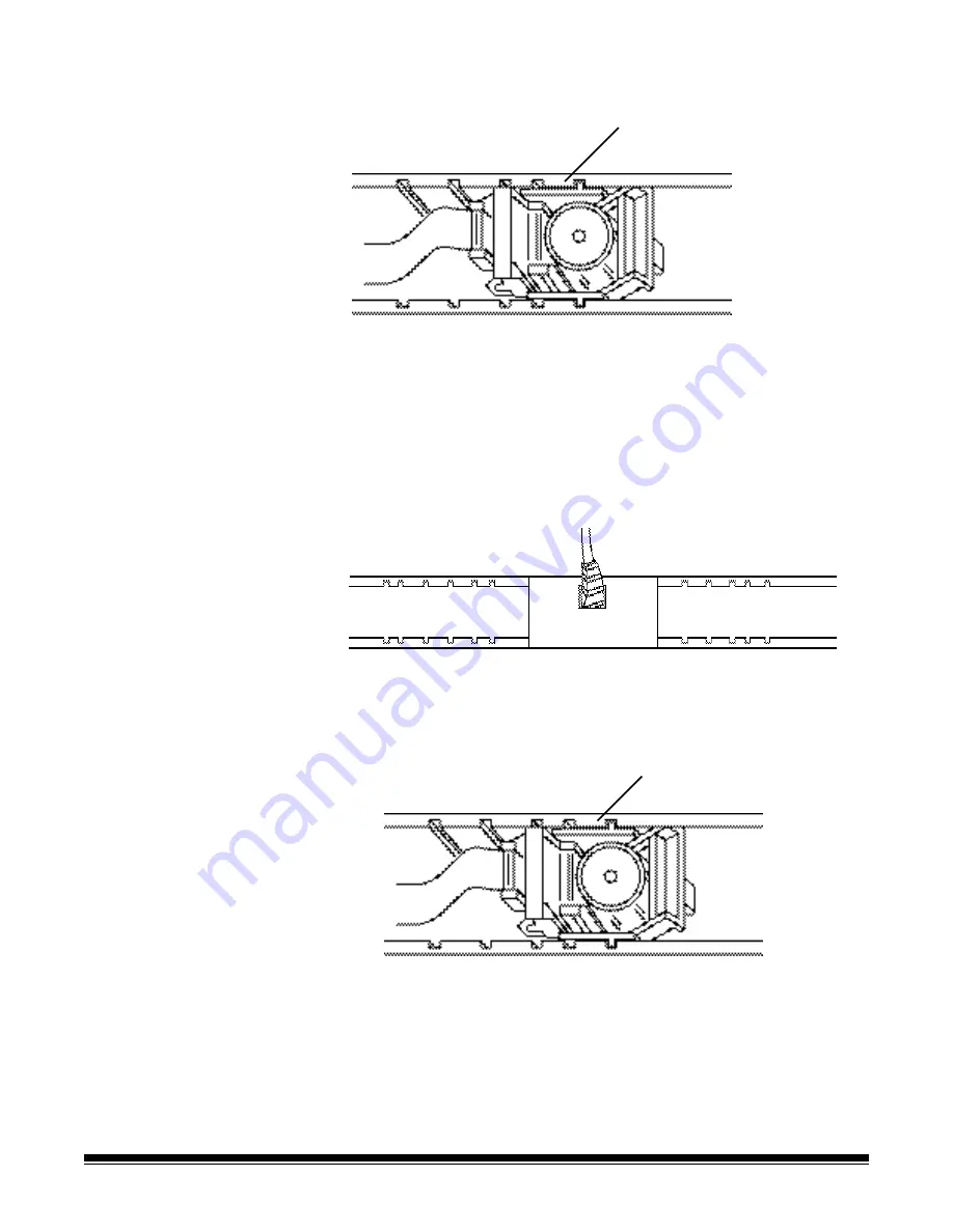
8. Slide the green ink cartridge carrier into the desired printer position. 

NOTE: You may change printer positions. Refer to the following 

section, “Setting the printer position.”

Setting the printer 
position

There are 11 possible positions for the printer. Make sure that the 
printer is in the correct position for your documents.

1. Remove the output tray and open the printer access cover.

2. Locate the printer positioning slots. 

3. Determine which position is suitable for your printing needs.

4. Slide the green ink cartridge carrier out of its slot. 

5. Slide the green ink cartridge carrier into the desired slot. 

NOTE: The side guides can also be adjusted (or offset) to 

accommodate the desired print position.

Printer positions

Printer position

Summary of Contents for I620 - Document Scanner

Page 1: ...P N 3E9836 A 61500 CAT No 875 9755 KODAK iNnovation Series Scanners...

Page 2: ...the FireWire cable 2 2 Attaching the power cord 2 3 Powering up the host computer 2 3 Scanner components 2 3 3 Using the Scanner 3 1 Turning the scanner on and off 3 1 Starting and stopping scanning 3...

Page 3: ...the pod 5 3 Cleaning the paper path 5 4 Cleaning the drive rollers feed module and separation roller tires 5 5 Cleaning the drive rollers 5 5 Cleaning the separation roller tires 5 6 Cleaning the fee...

Page 4: ...ents for scanning document feeder and output tray adjustments scanner calibration and how to scan documents Chapter 4 Using the Document Printer provides procedures for using and maintaining the Docum...

Page 5: ...l reduce black background bleed through which produces whiter images See Appendix A Accessories for more information Scanner features Excellent paper handling image quality and reliability Color or gr...

Page 6: ...ation CD This guide provides information for Quick Tips Guide A 61501 intended to be used as a quick reference for basic scanner use FireWire Installation Information A 61511 this installation informa...

Page 7: ...ot limited to the following Do not wear loose clothing unbuttoned sleeves etc Do not wear loose jewelry bracelets bulky rings long necklaces etc Hair length should be kept short using a hair net if ne...

Page 8: ...esigned to provide reasonable protection against harmful interference when the equipment is operated in a commercial environment This equipment generates uses and can radiate radio frequently energy a...

Page 9: ...use radio interference in which case the user may be required to take adequate measures Peoples Republic of China WARNING This is a Class A product In a domestic environment this product may cause rad...

Page 10: ...er computer and or more RAM may be necessary to obtain the rated throughput Intel PC or compatible with a Pentium IV 2 GHz processor PCI slot Microsoft Windows 2000 Professional Windows Me Windows 98S...

Page 11: ...lling the Kodak Driver software 1 Insert the Kodak i600 Series Scanners installation CD in the CD ROM drive The installation program starts automatically 2 Follow the on screen instructions to install...

Page 12: ...levator tray extender to accommodate long documents 2 Feed module provides smooth document feeding of various sizes thicknesses and textures CAUTION Moving parts avoid contact 3 Elevator tray side gui...

Page 13: ...n the transport or when a multi feed has been detected Illuminates when a user correctable error has been detected Illuminates when you need to call Service Refer to Chapter 6 Troubleshooting for comp...

Page 14: ...ging guides the scanner has an upper and lower imaging guide It is important to keep the imaging guides clean to obtain optimum image quality CAUTION Hot surface avoid contact 4 NFR rollers transports...

Page 15: ...wer to the scanner The scanner is packed with six power cords Choose the power cord appropriate for your location and connect it accordingly Connect the power cord first to the scanner then to the wal...

Page 16: ...st When completed the top green indicator light will remain on and constant If this does not occur refer to Chapter 6 Indicator lights for more information IMPORTANT Always power up the scanner to its...

Page 17: ...ton on the scanner to restart scanning after it has been paused Automatically pausing and resuming the scanner During scanning the scanner monitors its own internal image buffer memory In order to pre...

Page 18: ...first while using the gap release lever Ultrasonic multi feed detection is not recommended when using plastic sleeves NOTE When scanning documents in a clear protective sleeve the elevator tray side g...

Page 19: ...500 sheets of 75 g m2 20 lb paper Adjusting the side guides To accommodate multiple applications with variable feeding requirements the side guides can be adjusted for right left or center edge feedi...

Page 20: ...n either one of two positions In addition you can raise the front of the output tray to lift the front edge of the documents To raise or lower the back of the output tray 1 Lift the front of the outpu...

Page 21: ...ft the front of the output tray and pull it out of the detent position 2 Swing the height adjustment wire out from underneath the output tray and insert it into the groove on the printer access cover...

Page 22: ...in to 43 cm 17 in 1 Lift the front of the output tray and pull it out of the detent position 2 Place the output tray in the forward detent position 3 Gently push down on the left side of the output t...

Page 23: ...n Contact your Kodak Field Engineer 1 800 3KODAK3 to order the document extender Part No 5EF754 1 Lift the front of the output tray and pull it out of the detent position 2 Place the output tray in th...
Page 24: ...xit deflector The optional exit deflector aids in document stacking When feeding long documents it is suggested that the exit deflector be removed The exit deflector can be pulled out of place or push...

Page 25: ...the output tray end stop if necessary 6 Depending on how your scanner is set up your documents will automatically start scanning or you may need to press the Start Resume button to begin scanning Cont...

Page 26: ...that require special handling i e documents that are badly torn If you are in doubt about whether a damaged document can be transported through the scanner use the gap release lever and manually feed...

Page 27: ...feeds and document edges is properly adjusted for best performance Frequent calibration is not needed or recommended Image calibration Use the calibration target provided with your scanner Be sure to...

Page 28: ...or Log for more information You must wait at least 90 seconds before calibrating again Ultrasonics calibration Use only an A4 size 75 80 g m2 or lettersize 20 lb bond paper to perform an Ultrasonics c...

Page 29: ...will be displayed 4 Select Ultrasonics Calibration begins A confirmation box is displayed when calibration is complete 5 Click OK NOTE If calibration fails check the Operator Log for details See Chapt...

Page 30: ...view The document printer is unique in that the document print string can be configured to include both literal static information i e information that stays the same for each document such as batch n...

Page 31: ...he format HH MM where HH is in 24 hour format The hours and minutes are separated with a colon This field therefore uses five characters of the 40 character limit Control of the Printer any combinatio...

Page 32: ...r can be manually placed in 11 horizontal print positions Printer specifications Print positions Print positions Characteristic Description Maximum lines 1 Print locations horizontal 11 manually set P...

Page 33: ...er hole on the top of the ink cartridge 3 Rotate the ink cartridge until the bottom is face up 4 Gently press the paper clip against the side of the ink bladder untilasmall bead of ink appears on the...

Page 34: ...tridge carrier you will need to access the document printer 1 Remove the output tray 2 Open the printer access cover 3 Do the function you wish to perform i e change ink cartridge change the printer p...

Page 35: ...es 1 Access the document printer 2 Slide the green ink cartridge carrier out of its slot 3 Raise the locking bar if it is not already in the raised position 4 Remove the empty ink cartridge if one is...

Page 36: ...e sure that the printer is in the correct position for your documents 1 Remove the output tray and open the printer access cover 2 Locate the printer positioning slots 3 Determine which position is su...

Page 37: ...securely fastened and that the printer cables are not folded or creased Verify that the printer has been enabled through the ISIS or TWAIN Driver and that the expected print string has been specified...

Page 38: ...cluded with the i600 Series Scanners To order additional ink blotter strips refer to Chapter 5 Supplies and accessories 1 Open the pod 2 Locate the two ink blotter strips 3 Grasp an ink blotter strip...

Page 39: ...blotter strip in the transport channel Make sure that you align the blotter strips in the transport channel before pressing the adhesive side into the channel 8 Press the blotter strip firmly into the...

Page 40: ...rier because it is broken or is not getting a good electrical connection refer to Chapter 5 Supplies and accessories for ordering information To replace the ink cartridge carrier 1 Access the document...

Page 41: ...way from the ink cartridge carrier 6 Push the connector firmly into a new ink cartridge carrier 7 Replace the ink cartridge 8 Lower the locking bar around the ink cartridge 9 Slide the green ink cartr...

Page 42: ...a week and the paper path daily if you are using the Document Printer or if you are scanning carbonless paper or newsprint Depending on scanning volumes you may need to clean some parts more frequent...

Page 43: ...ers A vacuum cleaner to remove dust and debris from the scanner Item CAT No Kodak Feeder Consumables Kit for i600 Series Scanners 108 4755 Kodak Feeder Kit for Ultra Lightweight Paper for i600 Series...

Page 44: ...will need to open the pod to obtain access to the paper transport separation roller and imaging guides 1 Power down the scanner 2 Push up on the pod release lever 3 Open the pod 4 Close the pod when f...

Page 45: ...leaning sheet 3 Feed the cleaning sheet adhesive side up through the scanner in portrait orientation until all residue is removed from the drive rollers 4 Adjust the elevator tray and output tray side...

Page 46: ...pe If residue remains on the drive rollers feed module tires or separation roller tires after running a Transport Cleaning Sheet follow the cleaning procedures below NOTE When cleaning any rollers tir...

Page 47: ...te and wipe the separation roller tires with a roller cleaning pad For best results wipe parallel to the ribs in order to remove any residue between the ribs 6 Inspect the tires If the tires show sign...

Page 48: ...printer access cover to the right to release and remove the feed module 5 Manually rotate and wipe the feed module tires with a roller cleaning pad For best results wipe parallel to the ribs in order...

Page 49: ...ll the feed module by aligning the pins and fitting it into position Verify that the feed module is securely in place and moves freely after you install it 8 Close the pod 9 Close the printer access c...

Page 50: ...r hands with soap and water after performing maintenance procedures Refer to the MSDS for more information If cleaning the exposed side of the imaging guides does not result in satisfactory image qual...

Page 51: ...n of feeder performance multiple feeds stoppages etc indicate a need to change tires Change all the tires on the feed module and separation roller at the same time Feed Module and Separation Roller it...

Page 52: ...4 Push the release lever located underneath the printer access cover to the right to release and remove the feed module 5 If you are just replacing the feed module Insert the new feed module by aligni...

Page 53: ...e bottom housing with the other hand pull the upper housing up and away from the rollers 7 Remove one core assembly 8 Replace each tire by sliding the tire off the core 9 Install each new tire by gent...

Page 54: ...he slots on the lower housing 13 Press the upper and lower housings together until they snap into place 14 Reinstall the feed module by aligning the pins and fitting it into position Verify that the f...

Page 55: ...w separation roller Be sure to line up the slots on the separation roller with the holders 4 Push the separation roller holder back in place and close the pod To replace the tires 5 Replace each tire...

Page 56: ...ing the imaging guides The imaging guides should be replaced when they are heavily scratched and defects show in the image NOTE Handle the imaging guides carefully as to not put fingerprints on the gu...

Page 57: ...display Description Scanner is in sleep or lamp saver mode To return to Ready state press the Start Resume button on the scanner or enable scanning from the host or add paper to an empty elevator tra...

Page 58: ...for details If the condition cannot be cleared call Service Scanner warm up sequence Scanner is enabled Start Resume and Stop Pause buttons are available Scanner is enabled and scanning is allowed St...

Page 59: ...From the Drivers box select Kodak Scanner i600 and click OK The main Scan Validation Tool screen will be displayed 4 Select the Scanner icon 5 Select the Info tab 6 From the drop down box select Opera...

Page 60: ...tlet is not defective call a licensed electrician the power switch is on The scanner will not scan feed documents Make sure that the power cord is plugged in and the power is on all doors are complete...

Page 61: ...rtical streaks appear on the image Make sure that when you calibrate the scanner that you are using a good clean calibration target and that the imaging guides are clean Use the calibration target pro...

Page 62: ...sure the pod is completely closed Folded corner detected A folded corner was detected The transport was cleared and stopped Folded corner detected transport halted A folded corner was detected The tr...

Page 63: ...replace the separation roller tires and pre separation pad See Chapter 5 Maintenance for procedures Multi feed detected A multi feed has been detected and the transport has stopped Clear the multi fee...

Page 64: ...separation roller that are specially designed to feed light weight paper through the scanner transport This accessory includes the following 2 Feed Modules 2 Separation Rollers 5 Pre separation Pads...

Page 65: ...Group 4 compression uncompressed Scan Area Width 6 4 to 30 5 cm 2 5 to 12 in Length 6 4 to 66 cm 2 5 to 26 in ADF Capacity 500 sheets of 20 lb bond paper up to A3 Recommended Daily Volume Up to 20 000...

Page 66: ...PANY Commercial Imaging Rochester New York 14650 www kodak com go docimaging Kodak and Digital Science are trademarks of Eastman Kodak Company A 61500 1 2004 CAT No 875 9755 Eastman Kodak Company 2004...

Reviews: