


11
D. DOOR
① 12V
② GND
③ DOOR NO
④ DOOR COM
⑤ DOOR NC
D. DOOR
① 12V
② GND
③ DOOR NO
④ DOOR COM
⑤ DOOR NC
D. DOOR
① 12V
② GND
③ DOOR NO
④ DOOR COM
⑤ DOOR NC
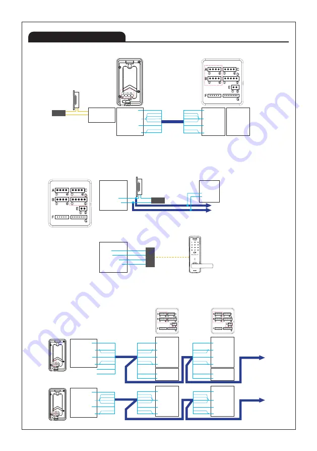
Product Wiring
■ Door camera connection (1:1)
■ Monitor's Door Opener Connection
■ CAM1 - Outdoor Camera, CAM2 - Outdoor Camera Connection (Ex-monitor Connection)
Indoor monitor
DC Door Lock
1. DC door lock connection
2. Using RF module for digital doorlock
Ex-Monitor
Ex-Monitor
External Power
for Door lock
RF Module
RF
⑤⑥
④ ③ ② ①
A B
1
1 3
4
Outdoor Camera
Indoor Monitor
①VCC(BLUE)
②GND(YELLOW)
③AUDIO(RED)
④VIDEO(WHITE)
①CA1 VCC
②CA1 GND
③CA1 AUDIO
④CA1 VIDEO
①CA2 VCC
②CA2 VCC
③CA2 VCC
④CA2 VIDEO
A
A
B
B
①COM(BLACK)
②NO(BROWN)
③NC(ORANGE)
ORANGE
DC Door Lock
W/Orange
W/Brown
W/Blue
Brown
Blue
W/Green
Green
ORANGE
W/Orange
W/Brown
W/Blue
Brown
Blue
W/Green
Green
CAMERA 1
CAMERA 2 & 420 SYSTEM
External Power
for Door lock
※ Door opener connected to the outdoor camera is available to be opened by each connected monitor separately.
※ Please select No or NC according to the specification of the door opener.
(You can check door opener's specification and it'll tell whether it's NO type or NC type.)
※ When using extended monitor, It may not work if the wire length is more than 50 meters.
At this time, reduce the wire resistance value by using four wires in a bundle of UTP cable.
※ Please select No or NC according to the specification of the door opener.
(You can check door opener's specification and it'll tell whether it's NO type or NC type.)
※ Please, ask supplier when you want to use rf module and digital doorlock
※ Remark: Ex-monitor means extended monitors
※ Remark: Ex-monitor means extended monitors
CAM1 : Door camera
CAM2 : Door camera
Indoor monitor
Ex-Indoor monitor
Ex-Monitor
Ex-Monitor
①VCC(BLUE)
②GND(YELLOW)
③AUDIO(RED)
④VIDEO(WHITE)
ORANGE
W/Orange
W/Blue
Blue
W/Green
Green
A
①VCC(BLUE)
②GND(YELLOW)
③AUDIO(RED)
④VIDEO(WHITE)
A
W/Brown
No connection
No connection
Brown
⑤⑥
④ ③ ② ①
A B
1
1 3
4
⑤⑥
④ ③ ② ①
A B
1
1 3
4
①CA2 VCC
②CA2 GND
③CA2 AUDIO
④CA2 VIDEO
B
ORANGE
W/Orange
W/Brown
W/Blue
Brown
Blue
W/Green
Green
CAMERA 2
①CA2 VCC
②CA2 GND
③CA2 AUDIO
④CA2 VIDEO
B
ORANGE
W/Orange
W/Brown
W/Blue
Brown
Blue
W/Green
Green
CAMERA 2
①CA1 VCC
②CA1 GND
③CA1 AUDIO
④CA1 VIDEO
①DATA
②GND
A
E
ORANGE
W/Orange
W/Blue
Blue
W/Green
Green
W/Brown
Brown
CAMERA 1
INNER DATA
①CA1 VCC
②CA1 GND
③CA1 AUDIO
④CA1 VIDEO
①DATA
②GND
A
E
ORANGE
W/Orange
W/Blue
Blue
W/Green
Green
W/Brown
Brown
CAMERA 1
INNER DATA
ORANGE
W/Orange
W/Brown
W/Blue
Brown
Blue
W/Green
Green
Summary of Contents for KCV-T701SM
Page 27: ...27...


