Manual
Wireless thermometer with clock
Art. 14200
Fa. Karl Koch Thermometerfabrik GmbH
Wolferstetter Weg 22
D – 97900 Külsheim
www.koch-thermometer.de
- 2 –
Below you will find essential information to install and use our new
wireless thermometer. Please read this manual carefully so that you can
become familiar with the unit’s functions and advantages.
Dear customer,
You have decided to purchase a Koch wireless product. Thank you for your
trust. This product was developed and produced using the latest
technology and testing methods available. Should you have problems with
the unit, please get in contact with our company directly. We welcome
your ideas and comments since we want to offer to you an optimal product
now and in the future.
Manual for wireless thermometer
Overview
This thermometer allows you to view temperatures at a base receiver sent
by up to three external transmitters (at the frequency 433,92 MHz). This
unit ships with a single transmitter, but additional transmitters may be
purchased at local retailers. The transmission range is up to 30 metres
(assuming optimal conditions), and the base receiver features additional
functions like a clock and a selector for °C or °F. You may view maximum
and minimum temperatures including the ability to set alerts for high
and low temperatures.
Contents of packaging
Your box should have the following contents:
- a receiving unit (Thermometer)
- a sensor (transmitter) with external temperature probe for fluids
- a plastic foot for tabletop use
Batteries
We strongly suggest the use of alkali batteries.
Receiving Unit: 2 x AAA Batteries (Micro)
Sensor (each): 2 x AAA Batteries (Micro)
Suggestions for optimal placement of the sensors
1. Like every thermometer you should not place the sensor in direct sun
light.
2. Never immerse the sensor and the receiving unit into water or expose
it to heavy rain. For measuring the temperature of fluids you need the
special temperature probe added in the box.
3. Bright backgrounds reflect temperatures while dark backgrounds absorb
them. The placement of the sensor in front of a dark background may
adversely affect temperature readings.
4. Do not place the sensor near the floor. Best results are achieved at
a height of about 1.5 metres.
5. You will achieve the best communications between the receiving unit
and sensor if you reduce the number of obstacles between them.
6. Please avoid using the sensor or the base station near computers, microwaves, wireless phones, net
adaptors or other units. They might disturb the transmission.
- 3 -
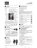
The receiving unit (Front side)
The display is divided into three vertical zones and additional small
symbols:
< front >
Displays
top: Clock
middle: Temperature at the base station
bottom: Temperature at the sensor (1-3; alternative display)
Number of the external sensors (1 – 3)
Sensor is actively transmitting to the base unit
Morning (AM) / Afternoon (PM) (alternative Display)
Low battery level (there is a separate indicator for the
base station and transmitter)
Temperature scale °C, or alternatively °F
Temperature alarm activated
Shown Minimum (MIN) / Maximum (MAX)
Auto-Scroll-Mode: the display cycles through the installed
sensors for five seconds each
((.)) Time alarm is activated
Buttons
MODE = Change time or display mode of time (12 or 24 hours)
CHANNEL = Choice of external sensor (1-3, as installed, standard
is only one, as adjusted)
CLEAR = Delete the actual saved Minima-/Maxima results
MAX/MIN = Recall the intermediate Minima-/Maxima results
ALERT = Activating and cancelling of the alarm
- 4 –
The base station (back side)
At the back side there are 2 buttons, a whole for a hook to hang the
station and a door for the battery compartment.
<back side>
Background illumination of the display
The display has a background illumination which can be activated by
pressing the button “Snooze/Light) on top of the base station.
The Transmitter
Tip
Before opening the cover remove
the bracket stand like shown in the
drawing. Afterwards you’ll see 4
screws, which you have to open.


