


Interface Modul
25
about the status of the instrument (e.g. in second intervals), then the
“Busy” LED will permanently blink.
The red “Error” LED lights when a calibration error is detected in a self-
test or when the software sends a command to the instrument that does
not exist.
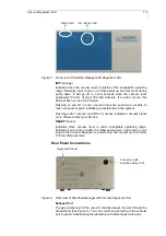
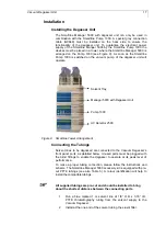
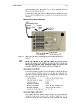
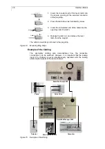
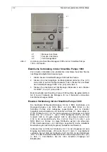
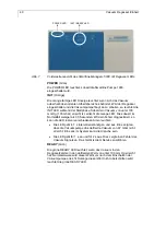
Back panel of the instrument
Connection to
Smartline Pump 1000
DIG.OUT or
autozero
RS232 connection
to the computer
1 2
3
DIG.IN
(Trigger
input)
AN.IN
(Data recording input)
AN.OUT
(Analog voltage
ouput)
Channel 1
Channel 2
Channel 3
Channel 4
Figure 13
Back panel view of the Smartline Manager 5000 with the Interface
Module
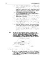
Please pay attention to the maximal voltage and current of the
inputs and outputs on the interface module and on the instruments
that will be controlled. If the maximum voltage and current are
exceeded, KNAUER is not liable for defective instruments!
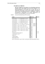
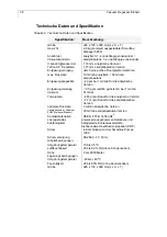
Analog Inputs (AN.IN)
To record from analog signals, up to four channels or instruments can be
connected with the interface module. The channels are independent of
each other, meaning all channels can be simultaneously operated from
either one system or various systems.
Voltage Range:
-2.56 to +2.56 V (bipolar mode)
Absolute maximum ratings:
-10 V to +10 V
Input impedance:
10 M
Ω
Maximum resolution:
24 bit
Minimum noise level:
7 µV (1 Hz, time constant 0.1 s)
Maximum data rate
up to 10 Hz (each channel)
Gain factor (for all channels): 1, 2, 4, 8, 16
Analog Outputs (AN.OUT)
The outputs distribute analog voltage signals, so that instruments
containing a respective input can be controlled. Depending on the
number of outputs, up to four instruments can be controlled. The outputs


