Page 14 of 32
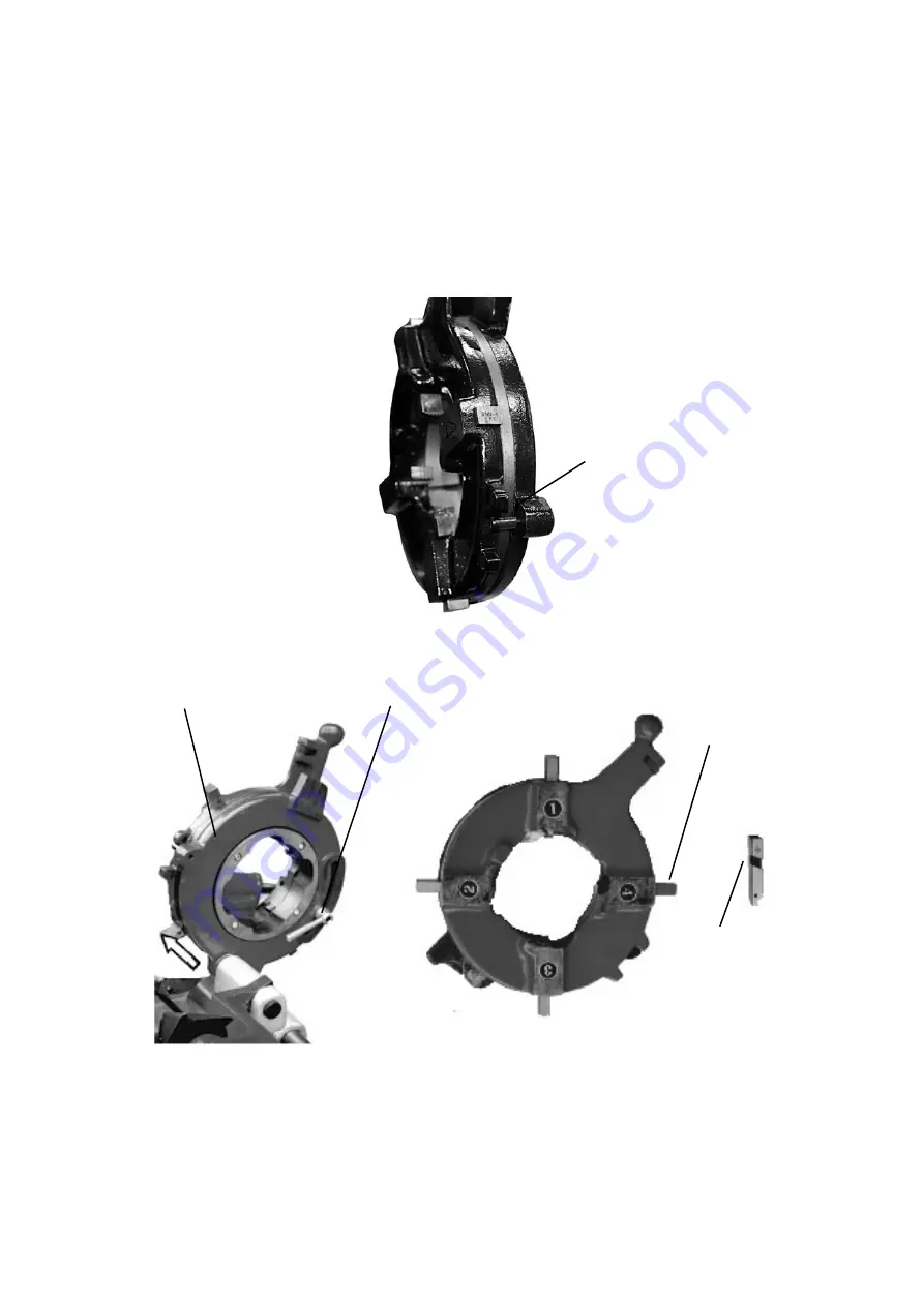
The index on the outside the die head represents the pipe diameter, and in Figure 3 below, the numbers 1, 2,
3, and 4 represent the assembly sequence for the die pieces.
1. Select a set of dies that match the diameter of the pipe.
Note:
The 1/2"-- 3/4 " and 1"--2" dies are installed
in the small die head (No. 1), while the 2-1/2" - 4" dies are installed in the big die head (No. 2).
2. Remove the die head from the sledge (see direction arrow in Fig.2), then:
a. Loosen the clamp lever (die head No. 1) or loosen the lock screw (die head No.2, see Fig. 1).
b. Rotate the curve disk to the highest position of the scale on the outside edge.
c. Tighten the clamp lever (die head No. 1) or tighten the lock screw (die head No. 2).
Lock Screw
Fig. 1
Curved Disk Clamp Lever
Die (4 pieces)
Die Tight Mouth
Fig. 2
Fig. 3
Summary of Contents for 49671
Page 21: ...Page 21 of 32 Wiring Diagram...


