Milling and Drilling Machine
OWNER’S MANUAL
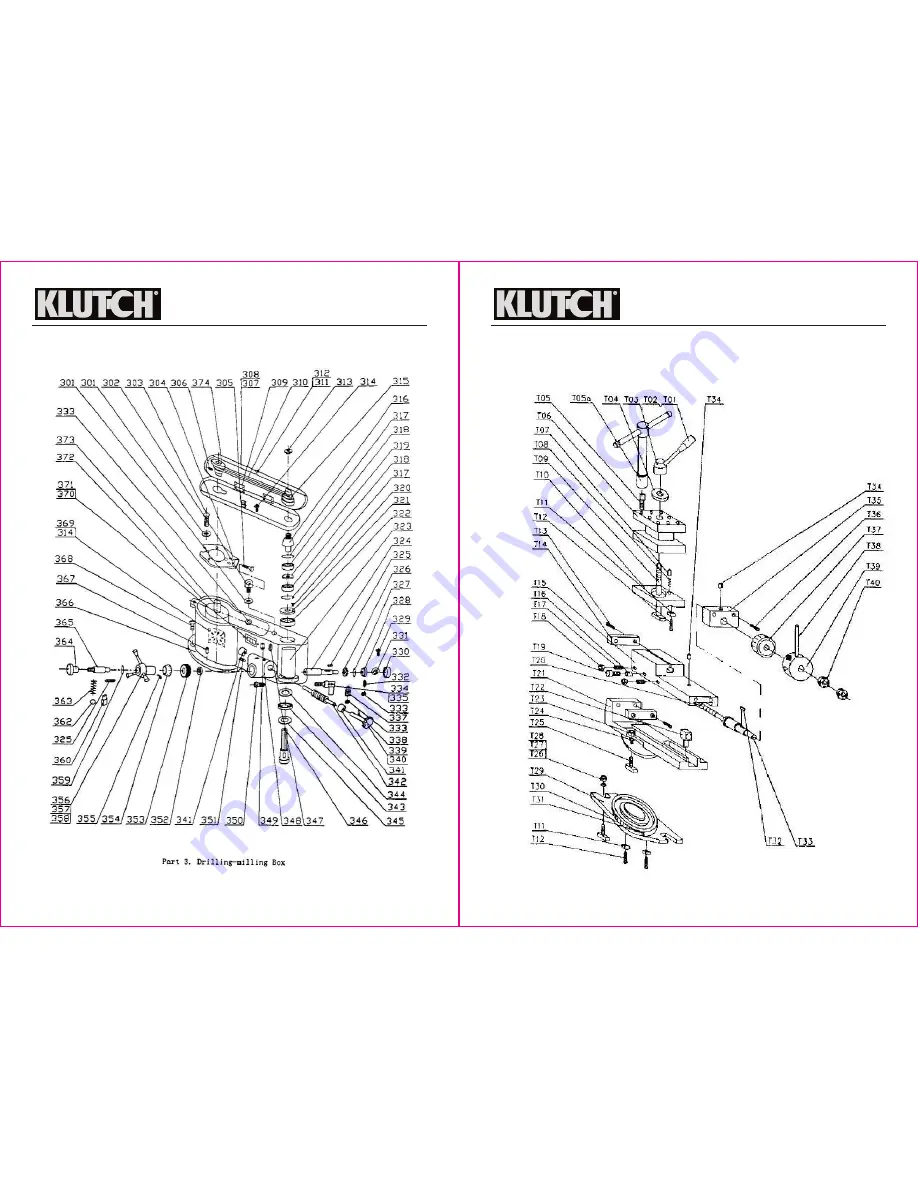
24 of 34
25 of 34
Part T. Tool Post
Page 1: ...he Machine Assembly 8 The Transmission System 8 The Electrical System 8 Controls 9 Before Each Use 10 Operating Instructions 10 Lubricating the Machine 11 The Drilling and Milling Feed 12 Longitudinal...
Page 2: ...can result in injury Using the milling and drilling machine in confined work areas may put you dangerously close to other cutting tools and rotating parts Do not use the milling and drilling machine w...
Page 3: ...tive safety measures reduce the risk of starting the tool accidentally Store the product when it is not in use Store it in a dry secure place out of the reach of children Inspect the tool for good wor...
Page 4: ...perly wired and in good electrical condition Always replace a damaged extension cord or have it repaired by a qualified electrician before using it Protect your extension cords from sharp objects exce...
Page 5: ...and milling motor by a button switch SB Fig 4 For safety purposes the machine should be grounded A 10A fuse should be fixed in front of the supply socket to maintain short circuit protection Milling...
Page 6: ...ls of the machine see page 12 Do not force the machine Tools do a better and safer job when used in the manner for which they are designed Plan your work and use the correct tool for the job Keep chil...
Page 7: ...relocked with the handle ATTENTION When the speed of spindle is too high a live center should be used The Tool Post The compound tool post mounted on the bench Fig 12 can be rotated to an angle with...
Page 8: ...Morse Taper No 2 shank 8 in Fig 1 Accessories and a drill chuck with key 6 which can be directly installed on the taper hole of the drilling milling spindle Note Before installing a chuck center conne...
Page 9: ...ig 33 which can result in injury 5 If using a taper shank with a flat end Fig 23 the shank can be directly inserted into the taper hole of the spindle taking care that its flat end is aligned with the...
Page 10: ...d assemblies reinstalled Adjusting the Lower Slide Beveled Gib After lengthy operation the beveled gib will be worn Therefore the tightening screw of the beveled gib should be adjusted as shown in Fig...
Page 11: ...e The following chart is based on a normal operation schedule Note This machine is a highly finished precision tool The bearing surfaces of the bench and below the lower slide are hand lapped If there...
Page 12: ...23 of 34 22 of 34 Milling and Drilling Machine OWNER S MANUAL Milling and Drilling Machine OWNER S MANUAL...
Page 13: ...Milling and Drilling Machine OWNER S MANUAL 24 of 34 25 of 34 Milling and Drilling Machine OWNER S MANUAL Part T Tool Post...
Page 14: ...Milling and Drilling Machine OWNER S MANUAL Milling and Drilling Machine OWNER S MANUAL 26 of 34 27 of 34...
Page 15: ...1 4 1 4 4 1 1 1 1 1 1 1 1 1 1 1 1 1 1 1 28 of 34 Milling and Drilling Machine OWNER S MANUAL 29 of 34 BED HEADSTOCK Part No GB297 84 GB1096 79 L H007 2 05 L H007 2 14 GB70 85 L H007 2 16 GB68 85 GB68...
Page 16: ...ing screw M4 6 washer gear scale ring plate spring handle body handle lever long handle cannula BM10 50 circlip for shaft 32 banking pin steel ball 6 spring Qty 1 1 1 1 1 2 1 1 1 1 1 1 1 3 1 1 1 2 1 1...
Page 17: ...lling Machine OWNER S MANUAL Part No GB37 GB876 86 GB1096 79 GB1155 74 GB70 85 GB812 88 GB923 84 GB97 85 GB4141 22 84 B 50 12 50 L H007 4 16 GB1155 74 GB1096 79 L H007 4 21 L H007 4 20 L H007 4 02 GB7...
Page 18: ...le remedy under this limited warranty or any other warranty related to the product We shall not be liable for service or labor charges or damage to Your property incurred in removing or replacing the...