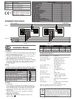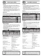
From Controller
1st Stage
2nd Stage
3rd Stage
Sounder
Beacon
+
-
+
-
1st Unit
2nd Unit
To Next Unit
Installation Manual
EN
Technical Specification:
Supply Voltage Range ................10-60V DC
Current – Sounder ...................... 8-40mA* (Typ. 30mA @ 24V, Tone 1)
Current – Xenon Beacon ............ 350mA peak @ 24V DC
(Where Fitted)
(60 single flashes per min.)
700mA peak @ 12V DC
(60 single flashes per min.)
Current – LED Beacon ................ 18mA (Flashing)*
(Where Fitted) ............................. 65mA (Static)*
Peak Sound Level .......................110-113 dBA at 1m*
(Typ. 105dBA @ 24V, Tone 1)
Number of Tones ........................ 64
Volume Control ........................... 20dBA typical
Remote Tone Switching ..............Provision for 3 alarm stages
(Negative voltage activation)
Operating Temperature ............... - 25°C to +70°C
Casing......................................... High Impact Polycarbonate/ABS
IP Rating ..................................... IP66
Synchronisation .......................... Automatic with Klaxon Nexus and
Sonos Sounders
*depends on selected tone and input voltage. See tone table for details.
EN54-3 certified on tones 1,2,3,6,7 & 13 & > 17V DC only.
Installation Instructions
The European directive “Waste Electrical and Electronic Equipment”
(WEEE) aims to minimise the impact of electrical and electronic
equipment waste on the environment and human health. To conform
with this directive, electrical equipment marked with this symbol must
not be disposed of in European public disposal systems. European
users of electrical equipment must now return end-of-life equipment
for disposal. Further information can be found on the following
website: http://www.recyclethis.info/.
Installation
a. The sounder is installed by first mounting the base unit and making the
external wring connections to the base. The head unit then automatically
connects when it is attached to the base.
b. The sounder head is separated from the base by unlocking the four
¼-turn fasteners in the corners of the sounder.
(Recommended screwdriver: Philips No. 2, min 100mm long).
c. Note that the head only fits onto the base one way around. If a beacon
is fitted, care should be taken when mounting the base to ensure that
the beacon will be positioned in the desired orientation after the
sounder is attached
Wiring
The sounder and beacon have separate wiring terminals. Each terminal is
duplicated to enable simple ‘daisy-chain’ connection of multiple units.
Controls
a. Tone Selection
The first and second stage alarm tones are independently set using
6-way dipswitches S1 and S2 respectively. The required settings are
shown in the table overleaf. The third stage alarm tone is pre-set to
complement the selected first stage tone as shown in the table.
b. Volume Control
The sound output of the unit can be reduced by up to 20dBA by
adjusting the potentiometer.
c. Beacon Flash Controls (If fitted)
The flash mode of the beacon can be altered using the 2-way
dipswitch marked
Type
CPR Reference
PNC-0024 Reference 0832-CPR-0615
PNC-0001 Reference 0832-CPR-0616
PNS-0001 Reference 0832-CPR-0617
Declared Performance
Essential Characteristics
EN54-3:2001+A1:2002+A2:2006 Subclause
Reproducibility
5.2
Operational performance
5.3
Durability
5.4
Dry Heat (operational)
5.5
Dry Heat (endurance)
5.6
Cold (operational)
5.7
Damp heat, cyclic (operational)
5.8
Damp heat, steady state (endurance)
5.9
Damp Heat, cyclic (endurance)
5.10
SO2 corrosion (endurance)
5.11
Shock (operational)
5.12
Impact (operational)
5.13
Vibration (operational)
5.14
Vibration (endurance)
5.15
Electrostatic discharge (operational)
5.16
Radiated electromagnetic fields (operational)
5.16
Voltage transients, fast transient bursts (operational)
5.16
Enclosure Protection
5.17
XENON BEACON
LED BEACON
Switch
Off
On
Off
On
1
60 flashes per min 30 flashes per min Single Flash Double Flash
2
Single Flash
Double Flash
Flashing
Static
Line
Terminal Marking
Sounder Positive Supply (10 to 60V DC)
+
Sounder Negative Supply (0V)
-
2nd Stage Alarm Control (Connect to 0V to activate)
S2
3rd Stage Alarm Control (Connect to 0V to activate)
S3
Beacon Positive Supply (10 to 60V DC)
+
Beacon Negative Supply (0V)
-
0832
07
0832-CPD-0615 (Sounder-LED Beacon)
0832-CPD-0616 (Sounder-Xenon Beacon)
0832-CPD-0617 (Sounder)

