


GL0052-03
– Envireau Mono-Tech Rainwater – Installation & Operation Guidelines
Page 24
Although the system can run from a 13 Amp switched socket outlet, this is not advised. In all instances a
separate RCD
MUST
be in circuit. The system draws approximately 4 amps at 240 volts AC. Whatever cable
is run to the local switch arrangement, the
maximum
cable size to enter the control unit should be 1.5mm
2
flexible TRS. Use a suitable joint box to convert if necessary. Permanently isolate, by fuse removal, this
supply until the total installation is complete.
DO NOT APPLY POWER UNTIL THEN
. The next stage is the
locating and fitting of the
Display
unit.
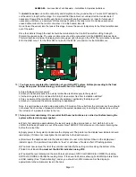
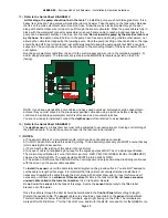
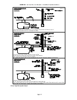
13)
Refer to the Guide Sheet DIAGRAM C
. The
display unit
is an important part of your system. Choose the
location carefully. The unit is designed to be mounted “flush” using a plaster-depth back box, or “surface”
using a surface back box. The display unit should be located in a visible position, in an area which is often
occupied. The display unit is wired back to the control panel, using standard “Alarm” cable. This cable should
be four cores at 1 amp per core rating (7/0.2 mm each core. Core colours red, yellow, black, blue). The cable
should be connected between the terminal block on the back of the display unit to the terminal block marked
“DISPLAY” in the control panel. The terminal blocks at both ends are marked R for RED core, Y for YELLOW
core, Bu for BLUE core and Bk for black core. The terminal block is marked DISPLAY and is top right
(facing) on the control panel Printed Circuit Board.
(
Note. If you wish to use the PUMP LOCK-OUT MODE or BMS contact on the DISPLAY unit and you need
to bring the feed from the contact back into the same location as the control unit, use 6 core cable. The two
remaining cores go into the PAIR of terminals at the back of the display panel. See the document on NON-
STANDARD SYSTEMS for details of the BMS CONNECTIONS and PUMP LOCK-OUT mode).
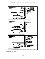
The next stage is the wiring in of the top-up solenoid valve.
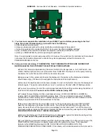
14) Locate the
solenoid valve
and install a local Switched Fused Spur (3 amp).
Wire in the Solenoid Valve
connector. Remove the screw on the back of the connector to release, then cable in to the spur using
suitable 3 core cable (TRS flex, 0.75 mm
2
). Feed the spur to the terminals in the controller marked PS
(Pressurised Solenoid) which are located left side, bottom terminal strip of the Printed Circuit Board in the
Controller. Use the earth connection provided.
Use maximum 1mm
2
flat Twin and Earth or equivalent flex
to make the entry into these terminals. Do not use oversize cores.
The next stage is the wiring in (and installation) of the pump.


