


GL0052-03
– Envireau Mono-Tech Rainwater – Installation & Operation Guidelines
Page 19
To
install
the
sensor
, uncoil the cable fully and straighten on the ground surface. You are NOT advised to
cut the cable to length at this stage. It is important that this cable is not unduly stretched so lubricate if
necessary. Draw all the cable through the duct, along with another draw-wire (or rope) for future use if
necessary, until there is a minimum of three metres of cable in the tank turret. Do not leave excessive
unused cable coiled in the turret or chamber. It is a trip hazard. Be safe.
Do not lower the sensor into the tank at this stage. Secure the sensor temporarily to the fitted turret bracket,
out of the water.
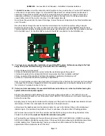
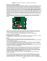
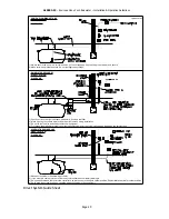
Once the cable is through the duct it should be terminated in the Control Panel after cutting to length.
Discard the unused cable. The sensor cable cores should be connected in to the SENSOR terminal block.
This terminal block is below the display terminals, upper right (facing) on the PCB. The terminals are marked
R for the RED core, Y for the YELLOW core, Bu for the BLUE core and Gn for the GREEN core
16)
You have now completed the installation of your GRAVITY system. Before proceeding to the final
stage, Set-up and Commissioning, you should check the following.
a) Are all pipework joints secure?
b) Have you taken precautions to quickly isolate the electrical supply to the system?
c) Is the storage tank full (or at least half-full) of clean water, free from installation detritus?
d) Are you aware of the location of all items of equipment, particularly the display unit?
e) Have you completed the external plumbing to appliances?
Note. It is permissible to install a stop-cock within 0.5 metres of the outlet from the controller but there should
not be less than 3 metres of pipework in total to the system appliance(s), including the header tank, without
the inclusion of a pressure vessel in the run.
17)
Set-up and commissioning. It is essential that these instructions are carried out before leaving the
system with electrical power applied.
a)
First of all, determine approximately the level of water in the storage tank i.e. Full, Half-full, etc. and
confirm that the depth sensor is out of the water. Now TURN OFF the stop-cock on the pump incoming
line
before the in-line
filter.
b)
Apply power to the system and observe the display unit. The pointer on the display level indicator should
read empty. (If it does not, investigate the connections to the depth sensor.)
c)
Now lower the depth sensor into the tank and allow it to rest on the bottom. Observe the display level
indicator again. The pointer will read either a “level” or will show a “fan-like” effect of flashing pointers.
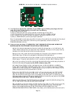
d)
You must now remove the lid of the controller and identify the setting controls along the bottom of the
Printed Circuit Board
You must set the LEVEL indication using VR2.
e)
To adjust the level display turn the small brass set-screw of VR2 CLOCKWISE to LOWER the reading,
ANTI-CLOCKWISE to RAISE the reading. Note. If the Level Indicator is showing FLASHING pointers this is
a HIGH reading (See “Troubleshooting”) and so you should turn VR2 clockwise. Set the display to
approximate to the actual water level in the tank.


