


15
About Digital Wireless Technology
About 2.4GHz Digital Wireless Signal
This innovative digital wireless solution integrates advance Frequency Hopping
Spread Spectrum (FHSS) technology. This technology greatly reduce the interference
that comes from other devices using the same radio frequency (2.4GHz), e.g. WIFI,
Bluetooth, Zigbee, cordless phone…etc. You now can enjoy a more pleasant wireless
surveillance quality without flicking and noisy image. However, weaker signal (lag
or still image) can be observed yet from time to time, depending on the environment
where the system is installed.
Complied with FCC part 15.247, ETSI (EN) 300 328, audio / video signals transmitted
out about or over 600 feet / 200 metres in line of sight should be supported. Line of sign
installation, though, is usually not a common practice. Factors affecting transmission
include microwave ovens or other high frequency electromagnetic waves. Reinforced
concrete walls, large scale metal products and metal furniture should not be located
near the camera or the receiver. Water creates an obstacle and should not be placed near.
Human bodies such as a person passing through may cause unstable signal quality
How to improve the wireless signal quality?
If possible, remove obstacles in between camera and receiver that might reflect the signal.
These could include furniture, cabinets, and walls. If you feel the wireless signal is not
good enough, place the receiver at a new angle or readjust its position to make an
improvement. Or simply relocate the camera closer to the receiver.
Why Image Compression?
In order to provide a private and interference free wireless service, this digital
wireless solution works on a 2Mb narrow hopping band. Different from traditional
2.4GHz analog signal, this digital wireless signal is compressed and presented
as Motion JPEG (MJPEG) format. By digitalizing and compressing the raw analog
data, the bandwidth is used more efficiently and securely. Consequentially, you might
observe an indent image line on a larger display monitor or plasma TV.
How to improve the image quality?
On QVGA size (ZOOM, zoom IN), pixel scattering is unavoidable. However, you can try
to zoom out the image to VGA size. By doing so, more pixels can be scattered on the
monitor. To have the best display performance, 32 inch or smaller monitor / TV is
suggested.
Getting Start
Camera
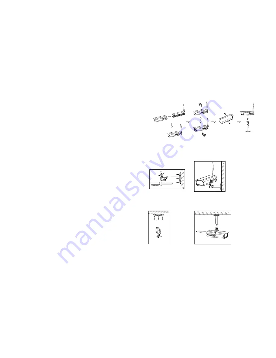
Assembly / Adjustment
A. Loosen U holder screws; slide the sunshield to ideal position.
B. U bracket can be installed on camera top side for ceiling mount.
C. Secure U holder with screws when done.
D. Adjust camera for proper view angle. Secure the stand with T-bolt when done.
Camera Wall Mounting
A. Secure camera stand on the wall
B. Secure camera U holder to the stand.
C. Adjust proper view angle then secure the joint with T-bolt.
Camera Ceiling Mounting
A. Secure camera stand on the Ceiling
B. Flip camera U holder to camera top, then secure U holder to camera.
C. Adjust proper view angle then secure the joint with T-bolt.
Step1: Hardware Set Up
4


