


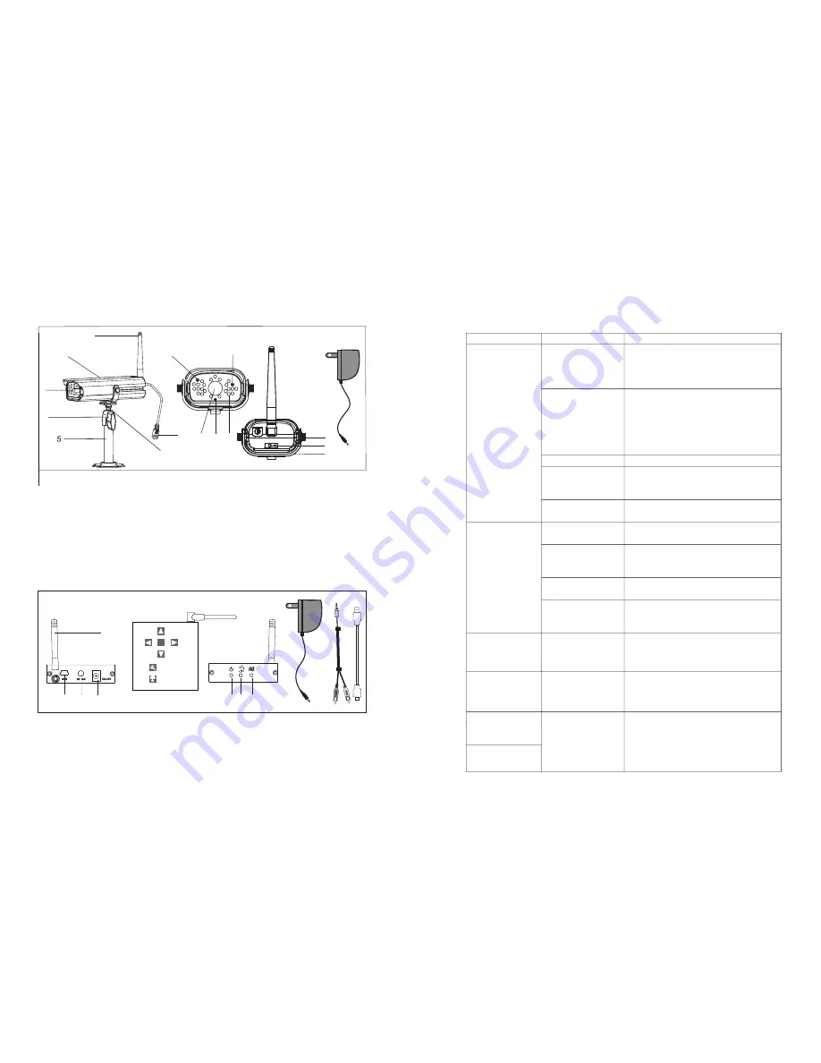
Knowing Devices Parts
16
Problem
Remedies
First identify the channel number, find the
corresponding camera. If camera power status
indicator (RED LED) lights off, check power
adapter and power cable connection.
First identify the image missing camera, draw the
camera near receiver then pair the camera to
desired channel. See Page 12 {Pairing Camera}
for detail. Once pairing completed and camera
is picking up by the receiver, camera Status
Indicator (GREEN LED)will light up.
Draw the camera near the receiver.
If possible, remove major obstacles in between
camera and receiver. Or relocate the camera to
proper location.
System Message
shows “N
Blank TV screen
shows [USB PC
Camera Mode] only
O Signal ”
Secure antenna to camera body tightly.
Adjust camera antenna and receiver position.
If possible, remove major obstacles in between
camera and receiver. Or relocate the camera to
proper location.
Keep WIFI router away from the camera and/or
receiver.
Low signal or unstable
signal
Keep working motors (hair dryer / heat fan / air
conditioner / water pump) or microwave oven
away from the camera and/or receiver.
Channel(s) disappear
during auto / manual
Scan or QUAD display
Go to menu; enable the channel(s). See Page 10
{Setting Auto / Manual Scan Sequence} or detail.
Dim / over bright
image at night time
Ideal low light vision distance is from 9 feet / 3
metres to 24 feet/ 8 metres.
. Adjust the camera to
have camera view fit in this distance.
Possible Causes
No power supply to
corresponding camera(s)
Channel is not paired
with camera yet
Service out of range
Signal been blocked
Camera antenna
connection loss
Antenna directional
limitation
Signal been blocked
Strong radio signal near
by
Strong electromagnetic
interference near by
Scan channel(s) been set
OFF
Low light vision distance
too short / too far.
Trouble Shooting
Before requesting service, please make the below checks. If you are in doubt
about some of the check points, or if the remedies indicated in the chart do not
solve the problem, please contact us.
Receiver Function
Buttons no response
USB Cable is plugged on
Connecting to TV, always use 5V power adaptor
to power up the receiver. Leave USB cable
unplugged PRIOR to TV connection.
Camera
Receiver
3
1.Antenna
2. Sunshield
3. Camera Lens
4. T- bolt
5. Camera Stand
6. Microphone
7. Power Jack
8. EDS
9. IR LED
10.Power LED
11. Link LED
12. U holder / U holder screw
13. Cam Pair
14. Power adaptor
13
14
back side
front side
12
12
4
6
10
11
8
3
9
7
1
2
3
1. Receiver antenna
2. USB out
3. A/V out
4. DC Power
5. Signal LED
7. Power LED
6. Pairing LED
8. Power supply
9. Phone jack to RCA cable
10. USB to USB Cable
1
2
3
4
6
7
5
8
9
10
M


