background image

14

Verify Anti-Tip Bracket Is Installed and 

Engaged

On models with a storage drawer:

1. Remove the storage drawer. To remove the storage drawer:

Pull the drawer straight out to the first stop.

Lift up on the back of the drawer and pull out.

2. Use a flashlight to look underneath the bottom of the range.

3. Visually check that the rear range foot is inserted into the slot 

of the anti-tip bracket.

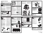
On models with a warming drawer:

1. Place your foot against the bottom front of the warming 

drawer and grasp the control panel with two hands as shown.

2. Slowly attempt to tilt the range forward. 

If you encounter immediate resistance, the range foot is 
engaged in the anti-tip bracket.

3. If the rear of the range lifts more than ½" (1.3 cm) off the floor 

without resistance, stop tilting the range and lower it gently 
back to the floor. The range foot is not engaged in the anti-tip 
bracket.

IMPORTANT: If there is a snapping or popping sound when lifting 
the range, the range may not be fully engaged in the bracket. 
Check to see if there are obstructions keeping the range from 
sliding to the wall or keeping the range foot from sliding into the 
bracket. Verify that the bracket is held securely in place by the 
mounting screws.

4. Slide the range forward, and verify that the anti-tip bracket is 

securely attached to the floor or wall.

5. Slide range back so the rear range foot is inserted into the 

slot of the anti-tip bracket.

IMPORTANT: If the back of the range is more than 2" (5.1 cm) 
from the mounting wall, the rear range foot may not engage the 
bracket. Slide the range forward and determine if there is an 
obstruction between the range and the mounting wall. Changes 
to the gas supply must be performed by a qualified service 
technician. If you need assistance or service, refer to the 
“Assistance or Service” section of the Use and Care Guide, or the 
cover or “Warranty” section of the User Instructions, for contact 
information.

6. Repeat steps 1 and 2 to ensure that the range foot is 

engaged in the anti-tip bracket.

If the rear of the range lifts more than 

¹⁄₂

" (1.3 cm) off the floor 

without resistance, the anti-tip bracket may not be installed 
correctly. Do not operate the range without anti-tip bracket 
installed and engaged. Please reference the “Assistance or 
Service” section of the Use and Care Guide, or the cover or 
“Warranty” section of the User Instructions, to contact 
service.

Level Range

1. Place a rack in oven. 

2. Place level on rack and check levelness of range, first side to 

side; then front to back.

3. If range is not level, pull range forward until rear leveling leg is 

removed from the anti-tip bracket. 

On Ranges Equipped with Storage Drawers:

Use


a ¼" drive ratchet, wrench or pliers to adjust leveling legs 

up or down until the range is level. Push range back into 
position. Check that rear leveling leg is engaged in the anti-tip 
bracket.

On Ranges Equipped with Warming Drawers:

Use a wrench or pliers to adjust leveling legs up or down until 
the range is level. Push range back into position. Check that 
rear leveling leg is engaged in the anti-tip bracket.

NOTE: Range must be level for satisfactory baking 
performance.

Complete Installation

1. Check that all parts are now installed. If there is an extra part, 

go back through the steps to see which step was skipped.

2. Check that you have all of your tools.

3. Dispose of/recycle all packaging materials.

4. Check that the range is level. See the “Level Range” section.

5. Use a mild solution of liquid household cleaner and warm 

water to remove waxy residue caused by shipping material. 
Dry thoroughly with a soft cloth. For more information, read 
the “Range Care” section of the Use and Care Guide.

6. Read the “Range Use” section in the range Use and Care 

Guide.

7. Plug in range or reconnect power.

8. Turn on surface burners and oven. See the Use and Care 

Guide for specific instruction on range operation. 

If range does not operate, check the following:

Household fuse is intact and tight; or circuit breaker has not 
tripped.

Range is plugged into an outlet.

Electrical supply is connected.

See the “Troubleshooting” section in the Use and Care Guide.

When the range has been on for 5 minutes, check for heat. If 
range is cold, turn off the range and contact a qualified 
technician.

Summary of Contents for W10440551A

Page 1: ...UCTIONSD INSTALLATIONDE CUISINIÈRESÉLECTRIQUESAUTOPORTANTES OUENCASTRABLESDE30 76 2CM Table of Contents Table des matières 2 IMPORTANT Save for local electrical inspector s use IMPORTANT À conserver pour consultation par l inspecteur local des installations électriques W10440551A ...

Page 2: ...gaged 14 Level Range 14 Complete Installation 14 Moving the Range 15 TABLEDESMATIÈRES SÉCURITÉ DE LA CUISINIÈRE 18 EXIGENCES D INSTALLATION 19 Outillage et pièces 19 Exigences d emplacement 19 Spécifications électriques 22 Préparation du plan de travail 22 INSTRUCTIONS D INSTALLATION 23 Déballage de la cuisinière 23 Mesures pour une hauteur appropriée 23 Ajuster les pieds de nivellement 24 Install...

Page 3: ... the safety alert symbol and either the word DANGER or WARNING These words mean follow instructions instructions DANGER WARNING Tip Over Hazard A child or adult can tip the range and be killed Install anti tip bracket to floor or wall per installation instructions Slide range back so rear range foot is engaged in the slot of the anti tip bracket Re engage anti tip bracket if range is moved Do not ...

Page 4: ...ly with installation clearances specified on the model serial rating plate The model serial rating plate is located inside the oven door on the right hand side oven door trim The range should be located for convenient use in the kitchen To eliminate the risk of burns or fire by reaching over heated surface units cabinet storage space located above the surface units should be avoided If cabinet sto...

Page 5: ...oduct Dimensions Freestanding Range Range can be raised approximately 1 2 5 cm by adjusting the leveling legs When installed in a 24 61 0 cm base cabinet with 25 63 5 cm countertop front of oven door protrudes 1 2 5 cm beyond 24 61 0 cm base cabinet Slide in Range Range can be raised approximately 1 2 5 cm by adjusting the leveling legs When installed in a 24 61 0 cm base cabinet with 25 63 5 cm c...

Page 6: ...ssociation 1 Batterymarch Park Quincy MA 02269 WARNING Improper connection of the equipment grounding conductor can result in a risk of electric shock Check with a qualified electrician or service technician if you are in doubt as to whether the appliance is properly grounded Do not modify the power supply cord plug If it will not fit the outlet have a proper outlet installed by a qualified electr...

Page 7: ...0R is used a matching UL listed 4 wire 250 volt 40 amp range power supply cord pigtail must be used This cord contains 4 copper conductors with ring terminals or open end spade terminals with upturned ends terminating in a NEMA Type 14 50P plug on the supply end The fourth grounding conductor must be identified by a green or green yellow cover and the neutral conductor by a white cover Cord should...

Page 8: ...ont to back If countertop is not level range will not be level Range must be level for satisfactory baking conditions INSTALLATION INSTRUCTIONS UnpackRange 1 Remove shipping materials tape and film from the range Keep cardboard bottom under range Remove oven racks and parts package from inside oven 2 To place range on its back take 4 cardboard corners from the carton Stack one cardboard corner on ...

Page 9: ...ing range into its final location check that the anti tip bracket will slide under the range and onto the rear leveling leg prior to anti tip bracket installation InstallAnti TipBracket 1 Remove the anti tip bracket from where it is taped inside the storage drawer or warming drawer 2 Determine which mounting method to use floor or wall If you have a stone or masonry floor you can use the wall moun...

Page 10: ...rd to continue installing the range using the following installation instructions ElectricalConnection U S A Only Power Supply Cord Direct Wire 1 Disconnect power 2 Remove the terminal block cover screws located on the back of the range Pull cover down and toward you to remove cover Rear position Front position Diagonal 2 options A Hold down screws B Terminal block cover WARNING Electrical Shock H...

Page 11: ... needed for the flexible conduit connection Assemble a UL listed conduit connector in the opening Feed the flexible conduit behind the black horizontal cross brace and through the strain relief allowing enough slack to easily attach the wiring to the terminal block Tighten strain relief screw against the flexible conduit 4 Complete installation following instructions for your type of electrical co...

Page 12: ...asher head screws from the aluminum terminal blocks 2 Connect the neutral center wire to the center terminal connector using one of the hex washer head screws Securely tighten screw 3 Connect the other 2 wires lines 1 and 2 to the outer terminal screws on the terminal block 4 Tighten strain relief screws 5 Replace terminal block cover with screw If your home has And you will be connecting to Go to...

Page 13: ...lines 1 and 2 under the other 2 screw clamps 5 Securely tighten the hex washer head screws to 35 lbs in 4 0 N m minimum torque to make proper electrical connection 6 Tighten the locking ring of the conduit connector 7 Replace the terminal block cover with screw 3 wire connection Direct Wire Use this method only if local codes permit connecting ground conductor to neutral supply wire 1 Loosen do no...

Page 14: ...t If the rear of the range lifts more than 1 3 cm off the floor without resistance the anti tip bracket may not be installed correctly Do not operate the range without anti tip bracket installed and engaged Please reference the Assistance or Service section of the Use and Care Guide or the cover or Warranty section of the User Instructions to contact service LevelRange 1 Place a rack in oven 2 Pla...

Page 15: ...wiring if necessary 4 Perform cleaning or maintenance 5 Reconnect wiring if necessary See Electrical Connection U S A Only section 6 Check that anti tip bracket is installed Look for the anti tip bracket securely attached to floor or wall Slide range back so rear range foot is under anti tip bracket 7 Check that range is level and reconnect power WARNING Tip Over Hazard A child or adult can tip th...

Page 16: ...16 Notes ...

Page 17: ...17 Notes ...

Page 18: ...ANGER ou AVERTISSEMENT Ces mots signifient Risque de basculement Un enfant ou une personne adulte peut faire basculer la cuisinière ce qui peut causer un décès Fixer la bride antibasculement au plancher ou au mur conformément aux instructions d installation Faire glisser de nouveau la cuisinière de façon à ce que le pied arrière de la cuisinière se trouve dans la fente de la bride antibasculement ...

Page 19: ...10113903A Biscuit W10113904A Exigencesd emplacement IMPORTANT Observer les dispositions de tous les codes et règlements en vigueur C est à l installateur qu incombe la responsabilité de respecter les distances de séparation exigées spécifiées sur la plaque signalétique de l appareil La plaque signalétique est située à l intérieur de la porte du four sur le côté droit de la garniture de la porte La...

Page 20: ... dessus Pour une installation en résidence mobile un câble ou cordon d alimentation à quatre fils doit être utilisé Le câblage de l appareil devra être revu Voir la section Raccordement électrique Dimensions du produit Cuisinière autoportante La cuisinière peut être surélevée d environ 1 2 5 cm en ajustant les pieds de nivellement Dans le cas d une installation entre des placards de 24 61 cm avec ...

Page 21: ...uminium 0 024 0 6 mm ou cuivre 0 020 0 5 mm Distance de séparation de 30 76 2 cm ou plus entre le dessus de la table de cuisson et le fond d un placard de bois ou de métal non protégé A Profondeur des placards supérieurs 13 33 cm B Largeur min de l ouverture 30 76 2 cm C Pour le dégagement minimal vers la partie supérieure de la table de cuisson voir la REMARQUE D Largeur min de l ouverture 30 76 ...

Page 22: ...prise de courant murale soit placée à portée de la position de service finale de la cuisinière Ne pas utiliser de câble de rallonge Préparationduplandetravail pourcuisinièresencastrablesuniquement Les bords latéraux de la table de cuisson de la cuisinière encastrable seront placés en chevauchement sur les extrémités du plan de travail Si la largeur de l espace disponible est de 30 76 2 cm et si la...

Page 23: ... sol aux 4 emplacements correspondant aux 4 coins de la partie inférieure de la table de cuisson voir illustration 2 Mesurer la distance entre le sol et la partie inférieure de la table de cuisson 3 La hauteur de nivellement correspond à la différence entre les 2 mesures prises à l étape précédente Cuisinières autoportantes 1 Mesurer la hauteur du plan de travail jusqu au sol 2 Mesurer ensuite du ...

Page 24: ... de nivellement arrière avant l installation de la bride antibasculement Installationdelabrideantibasculement 1 Ôter la bride antibasculement fixée par du ruban adhésif à l intérieur du tiroir de remisage ou du tiroir réchaud 2 Déterminer la méthode de montage à utiliser au plancher ou au mur Pour un plancher en pierre ou en briquetage on peut utiliser la méthode de montage au mur En cas d install...

Page 25: ...poser doucement sur le plancher Le pied de la cuisinière n est pas engagé dans la bride antibasculement IMPORTANT Si l on entend un claquement ou un bruit d éclatement lorsqu on soulève la cuisinière cela signifie peut être que la cuisinière n est pas bien engagée dans la bride Vérifier qu aucune obstruction n empêche la cuisinière de glisser vers le mur ou le pied de la cuisinière de glisser dans...

Page 26: ...e de courant électrique 8 Allumer les brûleurs de surface et le four Consulter le Guide d utilisation et d entretien pour des instructions spécifiques sur le fonctionnement de la cuisinière Si la cuisinière ne fonctionne pas contrôler ce qui suit Fusible grillé ou mal connecté Disjoncteur ouvert Cuisinière branchée sur une prise de courant reliée à la terre Circuit d alimentation sous tension Cons...

Page 27: ...Unis seulement 6 S assurer que la bride antibasculement est installée Vérifier que la bride antibasculement est bien fixée au plancher ou au mur Faire glisser de nouveau la cuisinière de façon à ce que le pied arrière de la cuisinière se trouve sous la bride antibasculement 7 Vérifier que la cuisinière est d aplomb et reconnecter la source de courant électrique AVERTISSEMENT Risque de choc électri...

Page 28: ... réservés Registered Trademark TM Trademark of KitchenAid U S A KitchenAid Canada licensee in Canada Marque déposée TM Marque de commerce de KitchenAid U S A Emploi sous licence par KitchenAid Canada au Canada 11 11 Printed in U S A Imprimé aux É U ...

Reviews: