Kisae Abso Charger 12V 100A Owner'S Manual Download Page 12


Page 

12 


Optional Remote Display Panel (ACRM1202) Connection:


For use on a single charger unit

:  

  Install the optional 

Remote Display Panel

 in the specific location. 

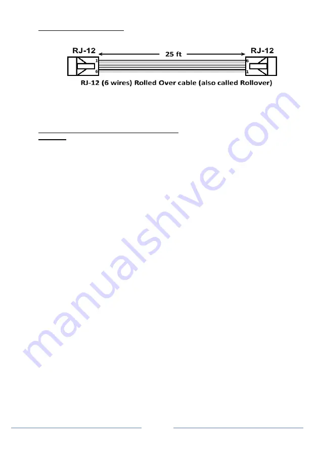
  The RJ12 Cable that is required is a RJ12 6 wired Rolled Over (Rollover) type. 


  Connect one end of the RJ12 cable to the 

Remote Port

 on the charger and the other end of the 

cable  to  the 

COM_1

  port  on  the 

Remote  Display  Panel

.  (

Do  not  use  COM_2  on  this 

installation).


  The 

Remote Display Panel

 is now ready for use. It is used as a secondary display to provide 

charger information. This panel share the same functionality as the display on the unit. 

For use with two charger units connected in parallel: (use same model only) 
CAUTION:


Use same model only, cannot be done with non-identical KISAE charger models). 

  Use the same procedure as above to install the first unit and the 

Remote Display Panel

  A second RJ12 cable is required for this installation. 

  Install the second charger close to the first charger. 

  Connect the second RJ12 cable 

between the second charger’s 

Remote Port

 to the 

COM_2

 port 

on the 

Remote Display Panel

  The 

Remote  Display  Panel

  is  now  ready  to  use.  Both  charger  displays  will 

show  ‘

CON

’ 

indicating the chargers are connected in parallel. And all the three push buttons on both chargers 
are disabled.  

  Before connecting the batteries to the chargers,  

o

  Connect Battery Bank 1 CH1 of Charger_1 to connect to CH1 of Charger_2.  

o

  Connect Battery Bank 2 CH2 of Charger_1 to connect to CH2 of Charger_2.  

o

  Connect Battery Bank 3 CH3 of Charger_1 to connect to CH3 of Charger_2.  

o

  The Common Ground of both chargers has to be connected together.  

Note: Damage to both chargers may occur if the above connections are not followed. 

  The setting for the combined chargers is based on the original setting on Charger_1. To readjust 

the combined charger setting, it has to be done through the 

Remote Display Panel

.  

Tips:

 During installation or unit setting, it is recommended to pre-set the desired charger setting on  

Charger_1 first before connecting the second RJ12 cable to Charger_2 because once Charger_2 
is connected all the three push buttons on the charger are disabled and the display will only show 

CON

’ and the setting can only be adjusted by using the Remote Panel. 


Summary of Contents for Abso Charger 12V 100A

Page 1: ...Abso Charger 12V 100A AC12100 24V 50A AC2450 Owner s Manual...

Page 2: ...Page 2...

Page 3: ...Abso Charger Misuse may result in damage to the unit and or cause harm or serious injury Product Numbers AC12100 Abso Charger 12V 100A AC2450 Abso Charger 24V 50A Document Part Number MU AC12100 Rev...

Page 4: ...STALLING THE CHARGER 10 5 UNIT OPERATION 13 6 SPECIFICATIONS 19 7 WARRANTY 20 Appendix A1 GEL Flooded AGM Setting CH1 CH2 CH3 Appendix A2 1 Lithium Setting CH1 Appendix A2 2 Lithium Setting CH2 3 Appe...

Page 5: ...an explosion WARNING Explosion hazard Do not use the unit in the vicinity of flammable fumes or gasses such as propane tanks or large engines Avoid covering the ventilation openings Always operate th...

Page 6: ...ere is no guarantee that interference will not occur in a particular installation If this equipment does cause harmful interference to radio or television reception which can be determined by turning...

Page 7: ...lgorithm During normal operation the charger will do a full charge cycle to float stage on Battery Bank 1 Once the float stage is reached the charger starts charging Battery Banks 2 and 3 together wit...

Page 8: ...Battery Bank 3 Chassis Ground The unit chassis has to be grounded properly to the common ground point on the system Digital Remote optional The Display Remote Part Number ACRM1202 sold separately is...

Page 9: ...e battery voltage reaches approximately 13 5V This timer is set to avoid battery overcharging The charger will override the Absorption to Float stage condition and goes to Float stage when it times ou...

Page 10: ...he mounting template on the right to mark the positions of the mounting screws Drill the 4 mounting holes and place the Charger in position and fasten the unit to the mounting surface See mounting loc...

Page 11: ...screws located at the top of the AC compartment cover Remove the top section of the AC Input wire strain relief located at the bottom of the base panel inside the AC wiring compartment by unscrewing t...

Page 12: ...s Remote Port to the COM_2 port on the Remote Display Panel The Remote Display Panel is now ready to use Both charger displays will show CON indicating the chargers are connected in parallel And all...

Page 13: ...display will then show the next menu to continue with other setting parameters NEXT Press the hold the key for longer than 5 seconds to RESET the charger Display will show RST and it will force the ch...

Page 14: ...27 V 0 54V AGM 0 21 V 0 42V For use when Battery Temperature Sensor is in use No setting on the unit is required and the unit will automatically sense the Battery Temperature Sensor when it is connec...

Page 15: ...rent L current in A Charging stages CH1 only Mode 2 Bulk and Absorption stage only Mode 3 Bulk Absorption and Float stage Battery temperature CH1 only Low Lo Normal nor High hi For Lithium battery typ...

Page 16: ...ed channel first and follows with 1 hour of 15 5V equalization process Consult or follow the instruction as provided by the battery manufacturer on how to check the battery electrolyte level and or re...

Page 17: ...g code will display The charger will recover automatically back to the maximum charging current when the environmental temperature drops to below 45 C Over Temperature Shutdown When the charger senses...

Page 18: ...alled The unit will shut down The unit will automatically recover when the battery temperature has reduced to 60 C 140 F For Lithium battery type setting High battery temperature 60 C 140 F is sensed...

Page 19: ...ith back lighting Charging status Battery Voltage Warning and Fault Code A01 E01 09 AC Input and DC Output Connection AC Input Connection Hardwire or AC with EU UK AZ plug DC Output Connection POS Hea...

Page 20: ...ive if products are deemed non working or malfunctioning the product may be returned to the purchasing store within 30 days of original purchase Any defective unit that is returned to the manufacturer...

Page 21: ...Page 21...

Page 22: ...Page 22...

Page 23: ...Page 23...

Page 24: ...Page 24...

Page 25: ...Page 25...

Page 26: ...Page 26 Appendix B...

Reviews: