6
INSTALLATION
INSTALLATION
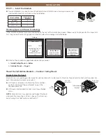
STEP 2 — Connect the Power Cable
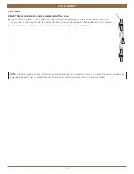
NOTE:
When power is connected to the motor, a green LED inside the programming button housing will flash to indicate the
blind is ready for operation.
■
■
Refer to the appropriate page based on your order:
■
➤
For a battery wand, see below.
■
➤
For a satellite battery wand, see page 8.
■
➤
For an optional 18V DC Power Supply. see page 9.
■
➤
For an optional 18V DC Power Supply with daisy-chain connections, see page 9.
■
➤
For an optional C-size satellite battery wand, see the instructions that came with the wand.
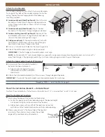
Plug the Power Cable into the Battery Wand
■
■
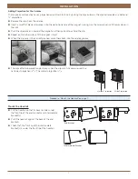
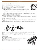
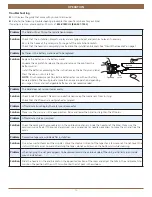
Inside of the headrail:
Connect the power cable (coming from the motor) into the socket on the battery wand.
Place the Battery Wand Inside the Headrail
■
■
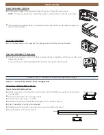
From the top of the headrail:
Place the battery wand
inside the headrail in a location where it will not interfere
with the operation of the blind.
Position its smooth,
curved side toward the tiltrod.
■
■
Carefully tuck excess wire into the headrail. Be sure to
avoid interference with internal headrail mechanisms.
STEP 3 — Install the Blind
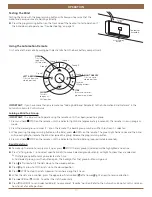
Attach the Magnetic Valance Clips to the Valance
The magnetic valance clips are adjustable for quick and easy valance attachment and have multi-position valance adjustment
capabilities.
■
■
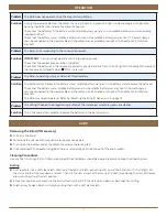
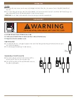
To install the clips, lay the valance face down on a protected surface with the back side up.
■
■
Insert the clip dovetail into the valance groove.
■
■
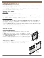
Twist the clip until it is straight with the clear tabs at the top of the valance.
■
➤
There are at least two clips per valance. For valances narrower than 36", position clips 5
1
⁄
2
" in from the ends of the valance.
For valances 36" or wider, position the clips 10" in from the ends of the valance. Additional clips should be spaced evenly
between the two end clips.
Tiltrod
Back of Headrail – Overhead View
Transceiver
Assembly
Battery Wand


