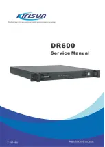
DR600 Service Manual
2. Product Controls and LED Indicator
Introduction
2.1 Product Controls
The appearance of the the DR600 repeater is shown in the Figure 2-1.
Figure 2-1 DR600 Appearance
No.
Part Name
No.
Part Name
1
Handle
2
Fan
3
LED Indicator
4
Power Switch
5
Grouding Rod
6
100~240V AC port
7
13.6V DC port
8
RX Interface
9
ACCY interface
10
Ethenet Interface
11
GPS interface
12
TX Interface
2
Summary of Contents for DR600
Page 1: ......
Page 37: ...DR600 Service Manual 33 ...
Page 110: ...DR600 Service Manual Figure 2 Rx Module Bottom Board PCB View 106 ...
Page 111: ...DR600 Service Manual Figure 3 Tx Module Top Board PCB View 107 ...
Page 113: ...DR600 Service Manual Figure 6 Baseband Mainboard Top Board PCB View 109 ...
Page 114: ...DR600 Service Manual Figure 7 Baseband Mainboard Bottom Board PCB View 110 ...
Page 116: ...DR600 Service Manual Figure 10 Power Board Top Board PCB View 112 ...
Page 118: ...DR600 Service Manual Figure 13 Enternet Board Top Board PCB View 114 ...
Page 119: ...DR600 Service Manual Figure 14 Enternet Board Bop Board PCB View 115 ...
Page 150: ...DR600 Service Manual Figure 21 Baseband Mainboard Schematic Diagram 146 ...


