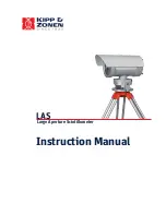
Kipp & Zonen LAS Instruction Manual Download Page 1

Instruction Manual

Large Aperture Scintillometer

LAS

Summary of Contents for LAS

Page 1: ...Instruction Manual Large Aperture Scintillometer LAS...

Page 2: ...nsure that it meets its published specifications The warranty included in the conditions of delivery is valid only if the product has been installed and used according to the instructions supplied by...

Page 3: ...indicate to the user important information The meaning of these symbols is as follows The exclamation mark within an equilateral triangle is intended to alert the user to the presence of important op...

Page 4: ...18 3 2 4 2 Installation of mast and mounting of sensors 19 3 2 4 3 Mounting enclosure solar panel and connecting wires 24 4 SOFTWARE 29 4 1 COMBILOG SUPPORT SOFTWARE 29 4 1 1 Setting communication pa...

Page 5: ...DEM 49 APPENDIX 3 MOUNTING ANTENNAS 51 APPENDIX 4 SERIAL PORT CONNECTIONS 53 APPENDIX 5 INSTALLATION FORM 55 APPENDIX 6 INSPECTION PROCEDURE 59 APPENDIX 7 SETTING DATE TIME COMBILOG 65 APPENDIX 8 FORM...

Page 6: ...0 0353 mm day 1 LMO Obukhov length m Pot potentiometer path length setting at Path length knob P air pressure Pa Press air pressure hPa conversion Pa hPa 1 hPa 100 Pa 1 mbar PUCN2 scaled Cn 2 m 2 3 Cn...

Page 7: ...is heated by the sun and decreases during the night due to radiative cooling RET Radio Evapo Transpiration system RS Roughness Sublayer Lowest part of the SL where the flow is influenced by individua...

Page 8: ...ge of storage of water in the soil which is the result of the amount of input into the soil e g due to rainfall or irrigation minus the amount of loss of water e g due to evapotranspiration surface ru...

Page 9: ...atalogger Slave Field station UCn2 Udemod and meteorol data 2 Mb Flash card or RS 232 Net radiation Soil heat flux Temperature humidity Wind speed direction RS 485 RS 485 Wireless RF communication Fig...

Page 10: ...s the data to daily fluxes of sensible and latent heat In Figure 1 an overview is shown of the LAS RET system Figure 2 shows the LAS BET system without the RF telemetry link LAS Transmitter LAS Receiv...

Page 11: ...ndly but offers also special tools for experts Handles multiple LAS BET and or LAS RET set ups Uses research grade processing algorithms Handles multiple processing algorithms4 Built in effective LAS...

Page 12: ...ally calibrated between 20 o C to 50 o C with an accuracy of 0 01 o C 0 o C Wind speed sensor Operating temperature 25 o C to 80 o C Range 0 60 m s 1 Voltage and power sensor Voltage and power heater...

Page 13: ...perating temperature 40 o C to 85 o C Frequency 2 4000 2 4835 GHz World wide license free Spread spectrum type Frequency hopping Wide band FM modulator Interface RS 232 RS 485 RS 422 Voltage Nominal 1...

Page 14: ...o Battery 85 Ah Tripods RET Radio Evapo Transpiration System Flux station for measuring fluxes at kilometre scale LAS or XLAS scintillometer Telescopes 2 5 m cable 2 sun weather cover Stainless steel...

Page 15: ...steel housing protection class IP65 containing o COMBILOG data logger plus 2 Mb PCMCIA Flash memory cards o Overvoltage protection o Barotranmsmitter o Solar controller o Battery 12V 85Ah o Solar pane...

Page 16: ...sentative for the area of interest away from forest edges or other rough surface elements A spot which is preferably near the centre of the path of the scintillometer as the LAS XLAS is most sensitive...

Page 17: ...ength o Be certain that the LAS XLAS is measuring in the Constant Flux Layer for reliable flux derivations of the Cn 2 signal using MOST depends on surface characteristics For detailed information the...

Page 18: ...he LAS Receiver data logger and sensors LAS Receiver LAS Transmitter Steel enclosure weather station UCn2 and Udemod signals Signals 12 VDC 2 4 GHz RF link 12 VDC 0 5 A 12 VDC 3 A window heater Solar...

Page 19: ...mperature and radiation measurements Terrain must be flat As the anchoring of the mast is based on 3 provided earth nails the soil must be strong enough to keep the loads also during rainy periods If...

Page 20: ...g zone of mast sections are indicated by red stripes printed on the mast sections Sensor arms a one sided a two sided and an U cross arm sensors temperature relative humidity net radiation wind speed...

Page 21: ...position of the mast the mast is erected by two persons While one person holds the mast in upright position the second person can determine the precise locations where the earth nails have to be driv...

Page 22: ...equently Especially after high wind speeds occurred If the soil seems not to be tight enough to keep the loads the anchoring has to be replaced by concrete foundations If the load lengthens the wires...

Page 23: ...3 Antenna 3 5 m To LAS Receiver 4 Air Temperature upper level T 2 7 m Two sided cross arm Opposite of radiation sensor 5 Net radiation Q or Rn 2 7 m Two sided cross arm South on N Hemisphere North on...

Page 24: ...emperature Net radiation Steel housing Temperature Solar panel Earth pin Antenna 0 45m 1 2m 1 7m 0 6m Figure 12 Overview of 4 m mast equipped with sensors antenna solar panel and steel enclosure for d...

Page 25: ...e than 1 plate burry them at the same depth It is safest to install plates at depth s of 3 cm from the side to prevent disturbance of the covering soil layer 3 2 4 3 Mounting enclosure solar panel and...

Page 26: ...mast i e the levelling of the net radiation sensor the alignment orientation of the antenna preferably using a small portable ladder Verify that the sensors and the RF link are working properly see s...

Page 27: ...rview of steel enclosure of weather station with RF Telemetry link LAS RET system The data from the LAS XLAS is collected by the MASTER COMBILOG via the RF telemetry link i e via the RF modem and the...

Page 28: ...27 Figure 17 Operational weather station of LAS RET system...

Page 29: ...28...

Page 30: ...will automatically start measuring once connected to a power supply The installation of the COMBILOG support software is carried out as follows Insert the installation CD into the selected drive incl...

Page 31: ...oftware will automatically scan for connected COMBILOG data loggers A list of found COMBILOG data loggers will appear on screen see Figure 19 Depending on the configuration mode of the COMBILOG data l...

Page 32: ...rogram s of each data logger can be found on the supplied CD In general the main configuration of the COMBILOG data loggers of the LAS systems is as follows A LAS system with RF telemetry link LAS RET...

Page 33: ...COMBILOG Type 1020 MASTER see Figure 20 Location LAS BET Name Kipp Filter freq 50Hz or 60Hz rejection Auto off Disabled LED Enabled Address 1 Protocol Profibus ASCII Baud rate 19200 Char format 8n1 A...

Page 34: ...d for desktop computers that are not equipped with a PCMCIA card reader The installation involves two steps the hardware installation of the reader in the desktop PC and the software installation of t...

Page 35: ...follow the prompts through the first screens clicking Next or Finish to move from screen to screen 3 When the program ends restart your system 4 After entering the serial number you will get a fully...

Page 36: ...ard should be used before removing the card from the device Important PCMCIA flash memory cards cannot be read without the CardWare software Important Never move delete or rename the COMBILOG log file...

Page 37: ...the supplied sensors this algorithm has been modified based on a compromise of calculating reliable fluxes and user friendliness Note that the output of the EVATION software i e calculation of the se...

Page 38: ...f small steps see Figure 26 First a working directory consists of an input subdirectory an output subdirectory and a configuration subdirectory has to be selected or configured In case one uses more t...

Page 39: ...38...

Page 40: ...S labelled data logger see 4 1 1 Setting communication parameters the actual measurements can be viewed via the Measure window see Figure 27 and Figure 28 In Table 4 the range and units of all measure...

Page 41: ...HFP1 sn W m 2 200 to 200 W m 2 8 Soil heat flux plate 2 G2 or HFP2 sn W m 2 200 to 200 W m 2 9 Net radiation Rn sn W m 2 250 to 1500 W m 2 10 Resistance upper PT100 PT100 sn 80 to 120 11 Resistance lo...

Page 42: ...actual measurement output of each sensors see Chan 1 to Chan X Description symbols 3 Turn knob clockwise 4 Turn knob counter clockwise 5 2 CALIBRATION COEFFICIENTS Some of the sensors of the LAS BET...

Page 43: ...10 Soil heat flux plate 2 G2 or HFP2 W m 2 11 Net radiation Q or Rn W m 2 12 Scaled Cn 2 PUCN2 m 2 3 13 Standard deviation of scaled Cn 2 m 2 3 14 Demod signal strength UDEMOD mV 15 Standard deviation...

Page 44: ...ements is of high standard care must be taken with the maintenance of the weather station A visual inspection routine of the weather station at regular intervals 2 weeks is therefore highly recommende...

Page 45: ...44...

Page 46: ...LAS LAS related problems e g power failure transmitter receiver units blown fuses misalignment poor visibility etc RF telemetry problems between receiver and weather station e g power failure misalign...

Page 47: ...adio2 The serial loop back adapter configures Radio2 to function as a repeater by looping serial data back into the radio for retransmission 3 Check that both RF modems operate in RS 232 mode see APPE...

Page 48: ...ght position for better signal strength Figure 31 Configuration COM port of PC Figure 32 Communication test of RF telemetry link Important This radio equipment is approved only for mobile and base sta...

Page 49: ...48...

Page 50: ...uch as Changing Interface baud rates Advanced addressing capabilities such as DT and HP see below etc In case two or more LAS RET stations are operational within several kilometres and the user s expe...

Page 51: ...50 Figure 33 Configuration screen and default settings of supplied RF modems...

Page 52: ...use special coaxial 50 Ohm antenna cable with excellent electrical and mechanical properties To mount the antenna at the LAS receiver side a universal antenna mounting system is supplied This mounting...

Page 53: ...alling the LAS XLAS and weather station Important This radio equipment is approved only for mobile and base station transmitting devices separation distances of 1 20 centimeters or more for antennas w...

Page 54: ...ommon 2 Computer RF Modem modem in RS 232 configuration Computer DB 9 Female RF Modem DB 9 Male Pin 1 Pin 1 Pin 2 Pin 2 Pin 3 Pin 3 Pin 4 Pin 4 Pin 5 Pin 5 Pin 6 Pin 6 Pin 7 Pin 7 Pin 8 Pin 8 Pin 9 Pi...

Page 55: ...54...

Page 56: ...quired for the EVATION data processing software Date Year Month Day Installed by Station name convenient to use in EVATION as working directory 1 Weather station sensors Sensor S N COMBILOG Channel no...

Page 57: ...to short long Mean signal strength at Receiver UDEMOD mV Path length Potentiometer setting Receiver PotLAS XLAS This corresponds to a distance of m See LAS Instruction Manual section 3 8 for conversi...

Page 58: ...eight calculator needs the following input data transmitter installation height receiver installation height the elevation of the transmitter and receiver site and the elevation plus position of a num...

Page 59: ...nt 1 0 500 Int point 2 3 750 Int point 3 7 5 1000 Int point 4 7 5 2300 Int point 5 20 3000 Int point 6 20 3500 Int point 7 18 3700 Int point 8 18 4000 Int point 9 25 4500 Receiver site RX 36 4700 3 30...

Page 60: ...atically when over current does no longer exist Constant red Controller is over heated 85 o C Disconnected Automatically when temperature has decreased Yellow flashing Battery voltage is too high 15 V...

Page 61: ...es in enclosure of LAS RET 1 Power terminal 2 Solar controler 3 Battery Measurement signal Power terminal with internal fuse Power signal cables Over voltage protection 12 VDC Power To PC RS232 Steel...

Page 62: ...wer check the RF telemetry link see step 4 Combilog 1020 U 3 xx Date dd mm yy Time hh mm ss LOG 0 253kb free 27d PCMCIA 1904kb free 100d Chan 1 xx units Chan x xx units Figure 40 Main menu of COMBILOG...

Page 63: ...e the stainless steel housing including the various connections over voltage protection and data logger Finally check the leveling of the radiation sensor and the mast see next step 6 Check the condit...

Page 64: ...e PC to the RS 232 interface of the COMBILOG Start the COMBILOG support software Scan for available COMBILOG data loggers Click on Utilities Read Logger and follow instructions 8 Check the LAS XLAS Fi...

Page 65: ...mounting construction for the LAS can regularly lead to a misalignment of the LAS c The display shows realistic values This indicates that the LAS is working fine Check if the signal strength Demod o...

Page 66: ...ynchronizing the data logger data and time 2 Manually using press rotary knob The press rotary knob on the data logger allows the user to modify the settings of the data logger manually By turning pre...

Page 67: ...enu cannot be accessed In order to enable this knob go to COMBILOG 1020 of the main menu by rotating the press rotary knob Press the knob briefly The configuration menu will be accessed Rotate the kno...

Page 68: ...between Set Date and Set Time rotate knob By pressing the knob briefly the date time can be changed Once the date time is correct press the knob briefly to confirm Set Date Set Time Auto off OFF LEDs...

Page 69: ...68...

Page 70: ...ge data to the card using the Write Raw Data function Go to Raw Access menu and select Write Raw Data The image files are available on the installation CD sub directory image files and are named accor...

Page 71: ...70 APPENDIX 9 CONNECTION PLAN LAS BET LAS RET Figure 47 Connection plan LAS BET system...

Page 72: ...71...

Page 73: ...72 Figure 48 Connection plan weather station LAS RET system...

Page 74: ...73 Figure 49 Connection plan scintillometer LAS RET system...

Page 75: ...n com Kipp Zonen USA Inc 125 Wilbur Place Bohemia NY 11716 United States of America T 1 0 631 589 2065 F 1 0 631 589 2068 kipp usa kippzonen com SALES OFFICES Go to www kippzonen com for your local di...

Reviews: