Vehicle Starting and Driving
S-11
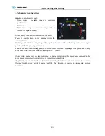
3. Tachometer working order
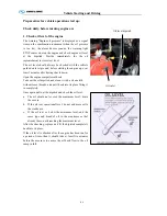
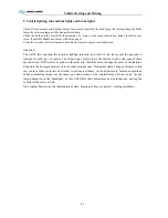
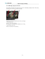
Indications on tachometer scale:
a.
Green zone – operating range of maximum
performance
b.
Yellow zone –
c.
Red zone – engine overspeed range (risk of
immediate engine damage)
Always observe tachometer while driving the vehicle.
Whenever possible keep engine running within the
economical range.
On downgrade, select an adequate gearbox speed ratio and monitor vehicle speed to avoid engine
operating in the danger range (red zone).
When the exhaust-brake is being operated on down grades, select an adequate gearbox speed ratio to keep
engine speed within efficient exhaust-brake operation
(
yellow
)
.
Always avoid engine over revving (red zone), as engine operation in this speed range can end up the
engine damage immediately or will seriously jeopardize its durability.
The yellow range with red reticle can be used occasionally when the exhaust-brake needs to be used at its
efficiency limit, however, at risk of engine durability. Therefore, do not operate in this range in a normal
or usual way.
Summary of Contents for XMQ6129Y series
Page 47: ...Technical parameter and complete vehicle description 0 T 1 TPMS OPERATION...
Page 48: ...Technical parameter and complete vehicle description 0 T 1...
Page 49: ...Technical parameter and complete vehicle description 0 T 1...
Page 50: ...Technical parameter and complete vehicle description 0 T 1...
Page 51: ...Technical parameter and complete vehicle description 0 T 1...
Page 52: ...Technical parameter and complete vehicle description 0 T 1...
Page 53: ...Technical parameter and complete vehicle description 0 T 1...
Page 54: ...Technical parameter and complete vehicle description 0 T 1...
Page 55: ...Technical parameter and complete vehicle description 0 T 1...
Page 56: ...Technical parameter and complete vehicle description 0 T 1...
Page 57: ...Technical parameter and complete vehicle description 0 T 1...
Page 63: ...Technical parameter and complete vehicle description 0 K 1 Lock1 Lock 2 Lock 3...
Page 157: ...Appendix A 4 Air braking schematic diagram...
Page 158: ...Appendix A 4 Electric schematic diagram of the complete vehicle 1...
Page 159: ...Appendix A 5 Electric schematic diagram of the complete vehicle 2...
Page 160: ...Appendix A 5 Electric schematic diagram of the complete vehicle 3...
Page 161: ...Appendix A 5 Electric schematic diagram of the complete vehicle 4...

