Maintenance and service
M-2
4.
When maintain the brake shoe ,do not damage the ring gear and sensor, clean the ring gear and
sensor at the same time. after maintenance ,do remember to put the sensor to the limited position
along the ring gear direction.
5.
Make sure that the power is in off position when remove and install the components, keep the
components clean and dry.
6.
Never change the fuse capability or connect the fuse in disorder.
7.
Change the indicator in time when it doesn’t work.
8.
Do not brush the ECU with water when cleaning it.
Note
: for details about the working theory of ABS and maintenance, please refer to the ABS instruction
book which is offered by provider.
Because of different allocation requirements, some of the vehicle model may not be equipped with ABS
system, please use correctly according to actual condition of vehicle.
Electrical system maintenance and service:
(1)
When battery is charged by external power supply, disconnect ECU control box to prevent outer
high voltage damage ECU (electric control unit).
(2)
When vehicle needs to weld, disconnect ECU. Don’t use multimeter to measure ECU control box.
(3)
Monitor voltage stability of generator regularly.
(4)
Parts dismantling must be carried out after electric has been shut off and should keep parts’
cleanness and dry.
(5)
Don’t change fuse capacity casually or bestride connect fuse.
(6)
When indicator doesn’t work, replace it timely.
(7)
Don’t use water to scour ECU when doing ECU cleanness.
(8)
Don’t use multimeter to measure ECU.
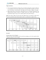
Tire transposition
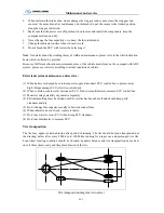
The tire may appear certain abrasion after period of running. The tire should be made transposition as
the drawing below after every 8000 km to 10000 km running for proper use and prolonged tire life.
Four-wheel locating condition should be checked, dynamic balance and tire transposition be made at
once if there shows early and irregular abrasion of the tire.
Tire transposition diagram (two axles)
Summary of Contents for XMQ6129Y series
Page 47: ...Technical parameter and complete vehicle description 0 T 1 TPMS OPERATION...
Page 48: ...Technical parameter and complete vehicle description 0 T 1...
Page 49: ...Technical parameter and complete vehicle description 0 T 1...
Page 50: ...Technical parameter and complete vehicle description 0 T 1...
Page 51: ...Technical parameter and complete vehicle description 0 T 1...
Page 52: ...Technical parameter and complete vehicle description 0 T 1...
Page 53: ...Technical parameter and complete vehicle description 0 T 1...
Page 54: ...Technical parameter and complete vehicle description 0 T 1...
Page 55: ...Technical parameter and complete vehicle description 0 T 1...
Page 56: ...Technical parameter and complete vehicle description 0 T 1...
Page 57: ...Technical parameter and complete vehicle description 0 T 1...
Page 63: ...Technical parameter and complete vehicle description 0 K 1 Lock1 Lock 2 Lock 3...
Page 157: ...Appendix A 4 Air braking schematic diagram...
Page 158: ...Appendix A 4 Electric schematic diagram of the complete vehicle 1...
Page 159: ...Appendix A 5 Electric schematic diagram of the complete vehicle 2...
Page 160: ...Appendix A 5 Electric schematic diagram of the complete vehicle 3...
Page 161: ...Appendix A 5 Electric schematic diagram of the complete vehicle 4...

