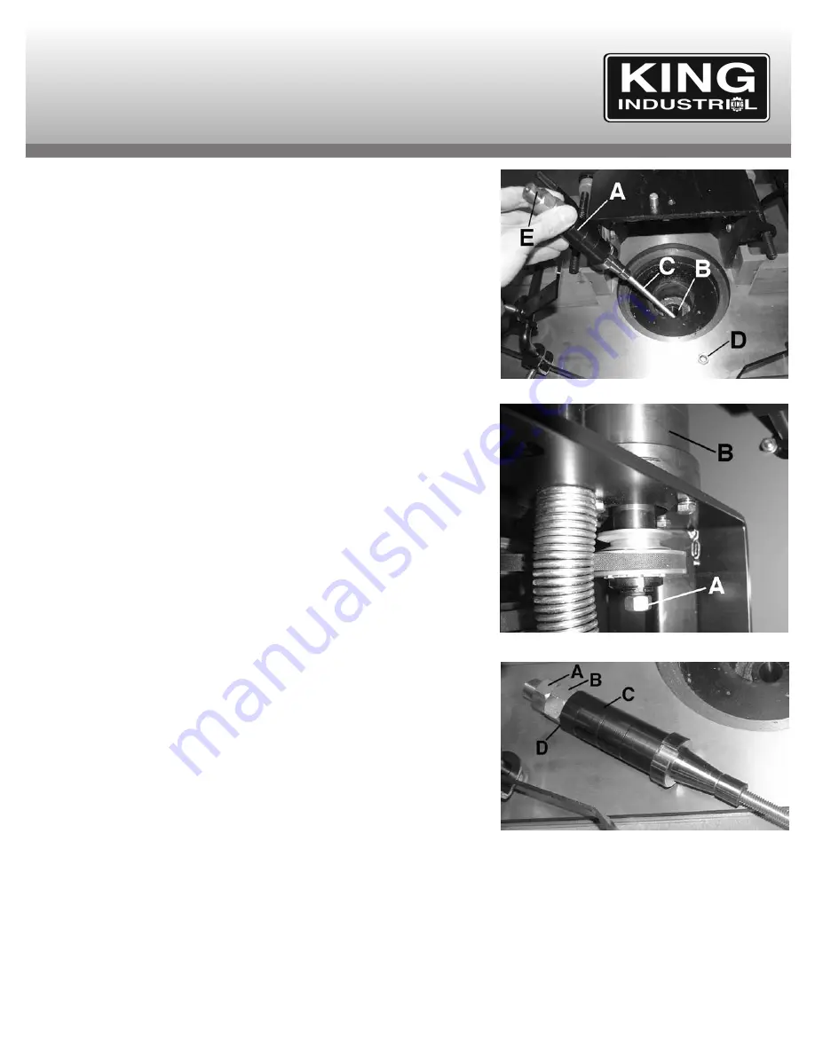
Changing Spindles
This shaper comes with a 1/2” and 3/4” spindle assemblies as standard accessories.
Please note that 1” (model: KW-088) and 1-1/4” (model: KW-089) spindle assemblies
are available as optional accessories. A spindle assembly (A) gets locked in a tapered
seat (B) Fig.10 at the top of the spindle housing and is held in place with a threaded
draw bar (C) and draw bar nut (D) below the spindle housing (B) Fig.11. To change a
spindle, proceed as follows;
1) To loosen the spindle, place a wrench on the flat (E) Fig.10 on top of the spindle and
another wrench on the draw bar nut (A) Fig.11. Unscrew the draw bar nut a few
turns only until there are no more threads visible at the end, tap the draw bar nut
gently upwards with a wooden block.
2) Now that the spindle popped out of the tapered seat, remove the draw bar nut and
pull the spindle assembly out of the spindle housing.
When reinstalling a spindle, make sure the draw bar is secure into the bottom of the
spindle. When placing spindle assembly into the spindle housing, make sure the
spindle seats snugly and the keyway slots align. Also make sure there is enough draw
bar nut threaded into the bottom of the draw bar to safely secure the spindle in place.
Installing/Changing Cutter
Your shaper operates at speeds of 8,000 and 10,000 RPM. Keep in mind that larger
cutters (3-1/2” or larger) must be operated at the lowest speed (8,000 RPM). Always
use the largest spindle size possible. DO NOT use a cutter that is not specifically
design for use on shapers. Make sure all spacers/collars/cutters are clean and not
damaged before installing them on a spindle.
To install/change a cutter, proceed as follows;
1) Select the appropriate spindle size, undo the top locknut (A) Fig.12 (left hand thread)
followed by the regular hex. nut (B) below it by placing wrench on the spindle flat
and a wrench on nut. Remove the spacers (C) from the spindle.
2) Place the appropriate spacer or rub collar at the base of the spindle for support.
3) Place the desired cutter on the spindle, make sure the rotation is correct for your
application.
4) Place spacers on spindle in order to reach the thread (D) of the regular hex. nut.
Secure spacer(s)/rub collar(s) and cutter with regular hex. nut and finally secure
using the locknut. Use a wrench to secure using the flat of the spindle to assist you.
Rub Collars
Rub collars are used when shaping curved or irregular workpieces, such as arched
doors or round tables tops. They also allow you to perform freehand work. There are
two types of rub collars; solid and ball bearing. Don’t confuse spacers with solid rub
collars. Spacer are rarely machined to close tolerances and not all ball bearings can be
used as rub collars. The illustrations on the following page (Fig13-15) show different
methods and arrangements for spindle stacking. These illustrations are for general reference only. Generally rub collars can be installed below,
above or between two cutters and can be used with patterns. These illustrations are shown with the guard removed for clarity. Do NOT attempt
to operate the shaper without guards or protective devices in place.
Collars are used to limit the depth of your cuts and are particularly useful when doing pattern work or irregular shaping. The amount of wood to
be removed from the workpiece is determined by the diameter of the rub collar and the cutting circle of the cutter. Here are a few hints for the
selection of rub collars.
1) Select the appropriate shaper cutter to match the your desired profile.
2) Determine if you will be working with a pattern or if the workpiece will rub against the rub collar.
3) Determine how much wood must be removed to achieve the desired profile.
ADJUSTMENTS & OPERATION
FIGURE 10
FIGURE 11
FIGURE 12


