Assembling Extension Table
The cast iron extension table extends your work surface area to provide support
for larger workpieces. Follow the instructions below to ensure your extension table
is flush and level with the shaper work table.
1) Make sure the contact surfaces are clean, free of dirt or grit.
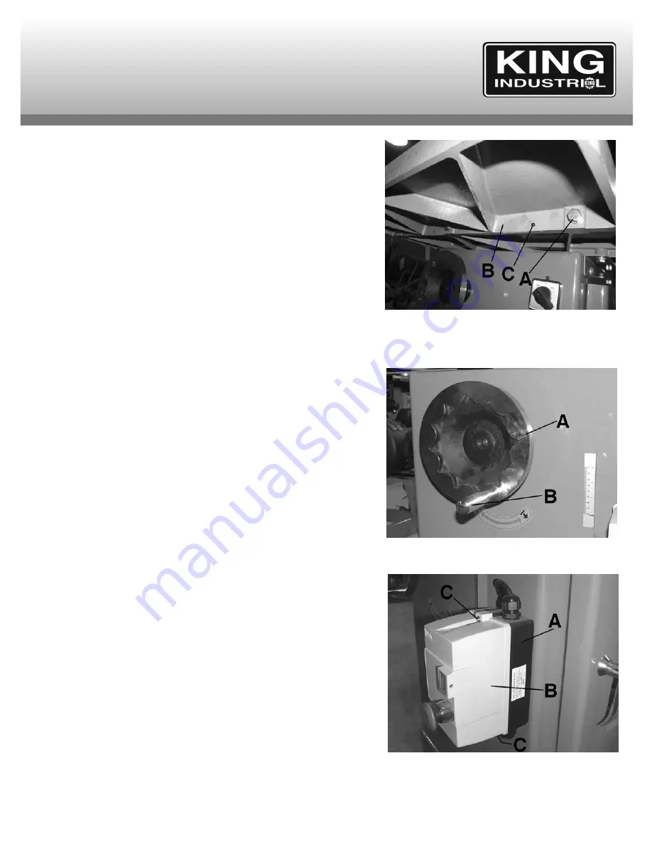
2) Put three bolts with spring washers and washers (A) Fig.4 through the extension
table (B) and thread them into the tapped holes at the front of the shaper. Leave
them loose for now.
3) Raise the extension up on one side and make sure it’s flush with the table edge.
Tighten the first bolt.
4) By raising or lowering the far end of the extension, locate the center of the
extension flush with the table. Tighten the center bolt.
5) The end of the extension table at the last bolt is probably not flush with the
surface of the table. Don’t be alarmed. Make sure the extension table is flush
with the first two bolts and that they are tight.
6) Now adjust the extension table, either up or down, at the last bolt. If necessary,
use a clamp and a couple of blocks to align the two surfaces. Tighten the final
bolt when the two surfaces are flush.
7) Once you’ve secured the extension table, inspect your results. If the extension
table is slightly tilted either up or down, adjustments can be made to level both
tables. This can be done by using set screws (C) located next to the three
mounting bolts. Place a straight edge on both the table and extension table,
adjust the set screws until the extension table is level with the straight edge on
the working table. Turn set screw clockwise to lift the table and counterclockwise
to lower the table. You may have to loosen the table mounting bolts slightly.
Assembling Handwheel Handle
The front mounted handwheel (A) Fig.5 comes without the steel handle (B)
installed, remove steel handle from loose items box and thread it to the handwheel
and secure.
Assembling Magnetic Switch to Front of Cabinet
The magnetic switch comes uninstalled to protect it during transport and needs to
be mounted to the front of the cabinet. To install;
1) The magnetic switch (A) Fig.6 gets installed to the right side of the cabinet,
below the forward/reverse switch.
2) First the magnetic switch cover (B) must be removed by unscrewing the two
Phillips head special screws (C). Note: These two specially designed Phillips
head screws are designed not to be removed. Unscrew them until the cover
comes off.
3) Secondly, open the cabinet right side access door, undo the hex. nuts at the
back of the magnetic switch, place magnetic switch against the cabinet and
align the screws with the mounting holes.
4) Insert screws into cabinet holes and secure from the inside of the cabinet using
the removed hex. nuts from step 3.
5) Once the magnetic switch housing is secured to the cabinet, reposition the cover
and tighten the two Phillips head special screws.
6) It is recommended to pull all the electrical wires from the magnetic switch inside
the cabinet.
FIGURE 4
ASSEMBLY AFTER UNPACKING
FIGURE 5
FIGURE 6


