ADJUSTMENTS & OPERATION
Adjusting Table Inserts
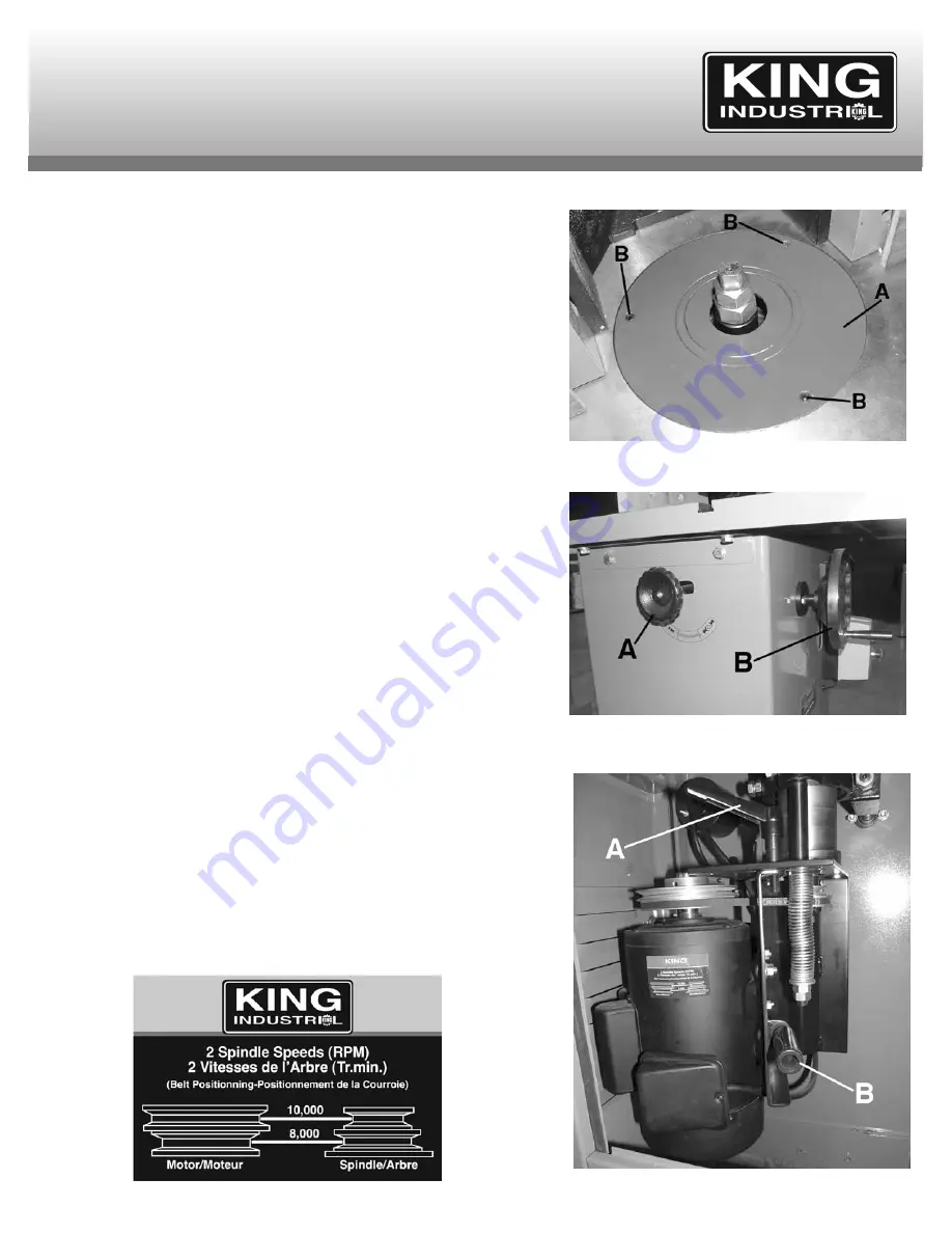
This shaper comes with 3 table inserts (A) Fig.16 which give you four possible
opening diameters in the shaper table surface. Use the smallest opening that a
particular cutter will allow. This offers more support for the workpiece and reduces
the amount of chips that can fall down into the machine. The correct spindle
opening will also allow any unused portion of the cutter to remain below the table
surface, increasing operator safety.
Table inserts must be flush with the top of the table. To adjust the table inserts,
proceed as follows;
1) Place a straight edge on top of the table inserts and the table and check to see
if the table inserts are flush all around with the top of the table.
2) If an adjustment is necessary, using the appropriate hex. key, turn the three set
screws (B) Fig.16 clockwise or counterclockwise to raise or lower the cast iron
table insert (A).
3) Inspect your results using the straight edge, adjust if necessary.
Adjusting and Locking Spindle Height
To adjust the cutter height;
1) Loosen the spindle height lock knob (A) Fig.17 counterclockwise.
2) Align your workpiece against the flat side of the cutter.
3) Adjust the cutter height by turning the front handwheel (B) clockwise to raise the
spindle and counterclockwise to lower the spindle.
4) Retighten the spindle height lock knob.
5) Cut a test sample and inspect your results, adjust if necessary.
Changing Spindle Speed
This shaper comes with 2 spindle speeds (8,000 and 10,000 RPM) which are
adjusted by changing the belt positioning on both the motor pulley and spindle
pulley. See speed/belt positioning nameplate Fig.18 as reference. To change
spindle speed, proceed as follows;
1) Open the hinged door at the back of the cabinet, loosen belt tension lock
handle (A) Fig.19 and then move the motor assembly to the right using the pivot
handle (B) to loosen belt.
2) Readjust the belt positionning to achieve the desired speed. See Fig.18.
3) Slide the motor back into position to tension the belt. The belt is properly
tensioned when there is approximately a 1/2” deflection in the center of the belt
when you press it with your thumb. Use good judgement, if the belt is too loose,
it will squeal or slip under load. If the belt is too tight, it will run hot and tend to
shake excessively.
4) Once the correct belt tension is achieved, retighten the belt tension lock handle
and close the hinged door.
FIGURE 16
FIGURE 17
FIGURE 18
FIGURE 19


