background image

To the Owner

�afety In�truction�

All  the  safety  and  operating  instructions  should  be  read 

before the product is operated.

Read  all  of  the  instructions  given  here  and  retain  them 

for later use. Unplug this projector from AC power supply 

before  cleaning.  Do  not  use  liquid  or  aerosol  cleaners. 

Use a damp cloth for cleaning.

Follow  all  warnings  and  instructions  marked  on  the 

projector.

For  added  protection  to  the  projector  during  a  lightning 

storm,  or  when  it  is  left  unattended  and  unused  for  long 

periods  of  time,  unplug  it  from  the  wall  outlet. This  will 

prevent damage due to lightning and power line surges.

Do  not  expose  this  unit  to  rain  or  use  near  water...  for 

example, in a wet basement, near a swimming pool, etc...

Do  not  use  attachments  not  recommended  by  the 

manufacturer as they may cause hazards.

Do  not  place  this  projector  on  an  unstable  cart,  stand, 

or  table. The  projector  may  fall,  causing  serious  injury 

to  a  child  or  adult,  and  serious  damage  to  the  projector. 

Use  only  with  a  cart  or  stand  recommended  by  the 

manufacturer,  or  sold  with  the  projector.  Wall  or  shelf 

mounting  should  follow  the  manufacturer’s  instructions, 

and  should  use  a  mounting  kit  approved  by  the 

manufacturers.
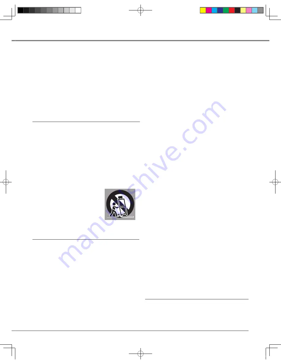
An  appliance  and  cart  combination 

should  be  moved  with  care.  Quick 

stops,  excessive  force,  and  uneven 

surfaces may cause the appliance and 

cart combination to overturn.

Slots and openings in the back and bottom of the cabinet 

are provided for ventilation, to ensure reliable operation of 

the equipment and to protect it from overheating.

The openings should never be covered with cloth or other 

materials, and the bottom opening should not be blocked 

by  placing  the  projector  on  a  bed,  sofa,  rug,  or  other 

similar  surface. This  projector  should  never  be  placed 

near or over a radiator or heat register.

This projector should not be placed in a built-in installation 

such as a book case unless proper ventilation is provided.

Never  push  objects  of  any  kind  into  this  projector 

through  cabinet  slots  as  they  may  touch  dangerous 

voltage  points  or  short  out  parts  that  could  result  in  a 

fire or electric shock. Never spill liquid of any kind on the 

projector.


Do not install the projector near the ventilation duct of 

air-conditioning equipment.

This  projector  should  be  operated  only  from  the  type 

of  power  source  indicated  on  the  marking  label.  If  you 

are not sure of the type of power supplied, consult your 

authorized dealer or local power company.

Do not overload wall outlets and extension cords as this 

can result in fire or electric shock. Do not allow anything 

to  rest  on  the  power  cord.  Do  not  locate  this  projector 

where the cord may be damaged by persons walking on 

it.

Do  not  attempt  to  service  this  projector  yourself  as 

opening  or  removing  Covers  may  expose  you  to 

dangerous voltage or other hazards. Refer all servicing 

to qualified service personnel.

Unplug this projector from wall outlet and refer servicing 

to  qualified  service  personnel  under  the  following 

conditions:

a. When the power cord or plug is damaged or frayed. 

b. If liquid has been spilled into the projector.

c. If the projector has been exposed to rain or water.

d. If the projector does not operate normally by 

    following the operating instructions. Adjust only those 

    controls that are covered by the operating instructions 

    as improper adjustment of other controls may result 

    in damage and will often require extensive work by a 

    qualified technician to restore the projector to normal 

    operation.

e. If the projector has been dropped or the cabinet has 

    been damaged.

f.  When the projector exhibits a distinct change in 

    performance-this indicates a need for service.

When replacement parts are required, be sure the 

service technician has used replacement parts specified 

by the manufacturer that have the same characteristics 

as the original part. Unauthorized substitutions may 

result in fire, electric shock, or injury to persons.

Upon completion of any service or repairs to this 

projector, ask the service technician to perform routine 

safety checks to determine that the projector is in safe 

operating condition.

PLC-EN.indd  

00-11-1   ::0

Summary of Contents for KX 400C

Page 1: ......

Page 2: ...2 NOTE Slight difference on OSD menu photographs between manual product display could be found Prior notice will not be given for any amendments on this manual PLC EN indd 2 2009 11 17 9 58 08...

Page 3: ...21 Auto Setup Function 21 Keystone Correction 21 Sound Adjustment 22 Remote Control Operation 23 Computer Input mputer Input 25 Input Source Selection Computer 1 2 25 Computer System Selection mputer...

Page 4: ...aning otherwise the lamp residual heat may result in shorten the service life of the projector and lamp greatly even damage them in a short time Safety Precaution CAUTION DO NOT SET THE PROJECTOR IN G...

Page 5: ...ojector through cabinet slots as they may touch dangerous voltage points or short out parts that could result in a fire or electric shock Never spill liquid of any kind on the projector Do not install...

Page 6: ......

Page 7: ...Terminals and Connectors Lamp Cover Power Cord Connector Speaker Filter Adjustable Feet Kensington Lock Kensington Security Slot Anti theft chain may opt to attach this slot to deter theft of the pro...

Page 8: ...l audio amplifier to this jack This jack recieves sources from AUDIO IN jack or pp 14 15 LAN Connection Terminal Connect the LAN cable Control Connect with computer by RS232 cable for PC controls Comp...

Page 9: ...the projector is in stand by mode Lights green during operations INPUT button Select an input source pp 25 32 MENU button Open or close the On Screen Menu Point VOLUME buttons Select an item or adjus...

Page 10: ...one distortion SELECT button Enter F Menu from S Menu for further operation Execute the selected item Expand or compress iamges in Digital zoom mode F MENU button Open or close full menu VOLUMN button...

Page 11: ...partment Replace the compartment lid Two AAA size batteries For correct polarity and be sure battery terminals are in contact with pins in compartment 1 2 3 Point the remote control toward the project...

Page 12: ...quality It is recommended to limit ambient lighting in order to obtain the best image All measurements are approximate and may vary from the actual sizes PLC EN indd 12 2009 11 17 10 00 47 Screen Siz...

Page 13: ...and the COMPUTER IN 1 terminal as input When the AUDIO OUT is plugged in the projector s built in speaker is not available Unplug the power cords of both the projector and external equipment from the...

Page 14: ...d in the projector s built in speaker is not available External Audio Equipment Audio cable Video S VIDEO VIDEO S VIDEO VIDEO cable Audio Video cable Video Audio Output S VIDEO Output VIDEO Output IDE...

Page 15: ...tput Component cable Cables used for connection Audio Cables Component Cable Component Cable Cables are not supplied with this projector Component Input Unplug the power cords of both the projector an...

Page 16: ...it is in Stand by mode and consumes a little electric power CAUTION The AC outlet must be near this equipment and must be easily accessible NOTE Inproper cable may influence product performance or ev...

Page 17: ...projector A PIN code consists of a three digit number Refer to the PIN code lock function in the Setting Menu on pages 43 for locking operation of the projector with your PIN code Enter a PIN code Use...

Page 18: ...of cooling fans is changed according to the temperature inside the projector Do not put the projector in a case before the projector is cooled enough If the WARNING indicator blinks or lights red see...

Page 19: ...nu or directly press F Menu button on the Remote Control to display Full Menu 1 2 3 Full Menu Top Control Point buttons Remote Control SELECT button AT LX640 AT LX640 AT LX640 1 1 MENU button SELECT b...

Page 20: ...ontal Vertical Clamp Display area H Display area V and Auto PC adj to adjust the parameters to match with the PC input signal format Screen For computer source iamage size is set in accordance with in...

Page 21: ...d e n o t s y e k keystone adjustment will be canceled The adjustable range is limited depending on the input signal Keystone Correction Auto setup function is provided to automatically execute the se...

Page 22: ...ff or press the VOLUME buttons The Mute function is also effective for the AUDIO OUT jack Press the SELECT button to switch the mute function On Off When the sound is turned off On is displayed Press...

Page 23: ...nction press the FREEZE button again or press any other button FREEZE button Display the Lamp status Lamp counter etc Information button Press the ZOOM buttons on the remote control to enter to the Di...

Page 24: ...is pressed TIME display NOTE See the previous page for the description of other buttons Image Mode button PATTERN button TIMER button BLANK button Choose 16 9 image size on screen display 16 9 button...

Page 25: ...Remote Control Direct Operation Menu Operation Press the F MENU button to display the On Screen Menu Use the Point buttons to select Input and then Press Point or the SELECT button Use the Point butto...

Page 26: ...stment function works to display proper images If the image is not projected properly a manual adjustment is required There is no signal input from the computer Check the connection between your compu...

Page 27: ...ome computers cannot be fully adjusted with the Auto PC Adjustment function When the image is not provided properly with this operation manual adjustments are required The Auto PC Adjustment cannot be...

Page 28: ...he Point buttons to adjust the number of total dots in one horizontal period to match your PC image Total dots Use the Point buttons to adjust the horizontal picture position Horizontal Press F MENU b...

Page 29: ...d then Press Point or the SELECT button Use the Point buttons to select the desired item and then press the SELECT button Co mputer Input For the image projected on a blackboard This mode help enhance...

Page 30: ...the contrast Press Point 8 button to increase the contrast Press Point button to decrease the rightness press the Point button to increase the brightness Contrast Brightness Press Point button to lig...

Page 31: ...projected image can be also expanded by pressing the or the SELECT button on the remote control To exit the Zoom mode press any button except the ZOOM buttons and the SELECT buttons D Zoom Select Dig...

Page 32: ...S video S VIDEO Top Control INPUT button Remote Control VIDEO button Press the F MENU button to display the On Screen Menu Press Point buttons to select Input and then press Point or the SELECT butto...

Page 33: ...575i 480p 575p 720p 1035i and 1080i Auto COMPONENT VIDEO SIGNAL FORMAT VIDEO or S VIDEO COMPONENT The projector automatically detects an incoming video system and adjusts itself to optimize its perfo...

Page 34: ...proved halftone for graphics Cinema Dynamic For viewing pictures in a bright room Normal picture mode preset on the projector For the image projected on a blackboard This mode help enhance the image p...

Page 35: ...t button to select Image Adjustment and then press Point button or SELECT button Press Point buttons to select the desired item and then press the SELECT button to display the adjustment dialog box Pr...

Page 36: ...mage at the 16 9 wide screen ratio Press F Menu button on the Remote Control to display on screen menu Press buttons select Screen and then press Point button or SELECT button Press buttons select the...

Page 37: ...ting Press Point buttons to select OSD Setting and then press SELECT button or Point button Menu position This function is used to change the position of the On Screen Menu Select Menu position and pr...

Page 38: ...of some computers can be fully adjusted with the Auto PC Adjustment function When the image is not provided properly with this operation manual adjustments are required This function enables Input sea...

Page 39: ...lt Show the factory set logo Off Show the countdown display only Capture This function enables you to capture an image being projected to use it for a starting up display or interval of presentations...

Page 40: ...nged to your desired three digit number Press the SELECT button to select Logo PIN code change Logo Pin code dialog box appears use the Point buttons to enter the correct code The New Logo PIN code in...

Page 41: ...hanges to green blinking In this condition the projection lamp will be turned on if the input signal is reconnected or any button on the top control or remote control is pressed Shut down When the lam...

Page 42: ...System Selection P 39 The icon of Closed Caption is displayed in gray while it is not available The Closed caption is unavailable when On Screen menu and Timer are displayed Setting This function all...

Page 43: ...o correct and then enter the correct number Repeat this step to complete entering a three digit number After entering the three digit number move the pointer to Set Press the SELECT button so that you...

Page 44: ...Off Normal speed Set this function to Off when using the projector in non high altitude environment On Faster than Off mode Select this mode when using the projector in high altitudes where the fans a...

Page 45: ...This function records anomalous operations while the projector is in operation and use it when diagnosing faults Up to 9 warning logs are displayed with the latest warning message at the top of the li...

Page 46: ...n Press the INFO button on the remote control to display the Information Menu INFO button Remote Control Press Input on the Top Control and then press SELECT button to display on screen menu Press the...

Page 47: ...nplug the AC power cord and reconnect it and then turn the projector on once again to verify operation If the projector cannot be turned on and the Warning indicator still lights red unplug the AC pow...

Page 48: ...dusty smoky environments when you operate the projector Usage in these environments may cause poor image quality When using the projector under dusty or smoky conditions dust may accumulate on a lens...

Page 49: ...e a small amount of mild detergent and finish with a soft dry cleaning cloth Avoid using an excessive amount of cleaner Abrasive cleaners solvents or other harsh chemicals might scratch the surface of...

Page 50: ...ace the lamp with a new one and secure the two 2 screws Make sure that the lamp is set properly Close the lamp cover and secure the screw 4 Loosen the screw and open the lamp cover 2 Connect the AC po...

Page 51: ...SHOULD BE TAKEN If a lamp explodes disconnect the projector s AC plug from the AC outlet immediately Contact an authorized service station for a checkup of the unit and replacement of the lamp Additi...

Page 52: ...Logo select function Input signal switches automatically or does not switch automatically Make sure Input search function is adjusted properly when the projector is on and you press the input button a...

Page 53: ...OUT is plugged in the projector s built in speaker is not available Is the image projected You will hear the sound only when the image is projected The color is strange Check the Input signal color sy...

Page 54: ...the projector with referring to Indicators and projector Condition The exclamation mark appears on the screen Your operation is invalid Operate correctly Top control does not work The top control is...

Page 55: ...s abnormally high The projector cannot be turned on When the projector is cooled down enough and the temperature returns to normal the POWER indicator stops blinking and the projector can be turned on...

Page 56: ...x 768 1600 x 1200 UXGA 1600 x 1200 1600 x 1200 1600 x 1200 832 x 624 75 SVGA 800 x 600 56 800 x 600 60 800 x 600 75 00 800 x 600 85 800 x 600 72 800 x 600 55 800 x 600 61 800 x 600 600 1280 x 1024 128...

Page 57: ...eFULL MENU will display Use arrow button to select network icon figure 1 2 Press SELECT or to enter network menu figure 2 3 Use arrow button to select network settings and the press SELECT figure 3 fi...

Page 58: ...ss select to check IP address 5 Enter the IP address obtained by step 4 into the address bar figure 6 Format http IP address LAN DHCP ON IP Address Subnet Gateway DNS set cancel Network Setting 6 Set...

Page 59: ...1 Computer In 2 Monitor Output Terminal Mini D sub 15 pin x 1 Control Port Connector D sub 9 pin x 1 Audio Output Jack Mini Jack stereo x 1 variable LAN Connection Terminal 100 Base TX 100Mbps 10 Bas...

Page 60: ...Clock 9 13 10 12 11 14 15 RX RX TX TX TX RX 2 3 4 876543 21 5 6 7 8 1 LAN TERMINAL CONTROL PORT CONNECTOR D sub 9 pin R X D T X D SG RTS CTS Serial 1 2 3 4 5 6 7 8 9 Appendix Write down the PIN code n...

Page 61: ...61 Dimensions UNIT MM IT MM Screw holes for ceiling installation Screw M4 rew M4 M4 Depth 10 0 Appendix PLC EN indd 59 2009 11 17 10 03 52...

Page 62: ...PLC EN indd 60 2009 11 17 10 03 53...

Reviews: