


Sirius Capacitor Module
–
User Manual
Model Number -7100-48-B-2C-M-SD-A-FL
This manual is subject to change without notice and at the sole discretion of Kilowatt Labs, Inc.
Kilowatt Labs, Inc. |
19
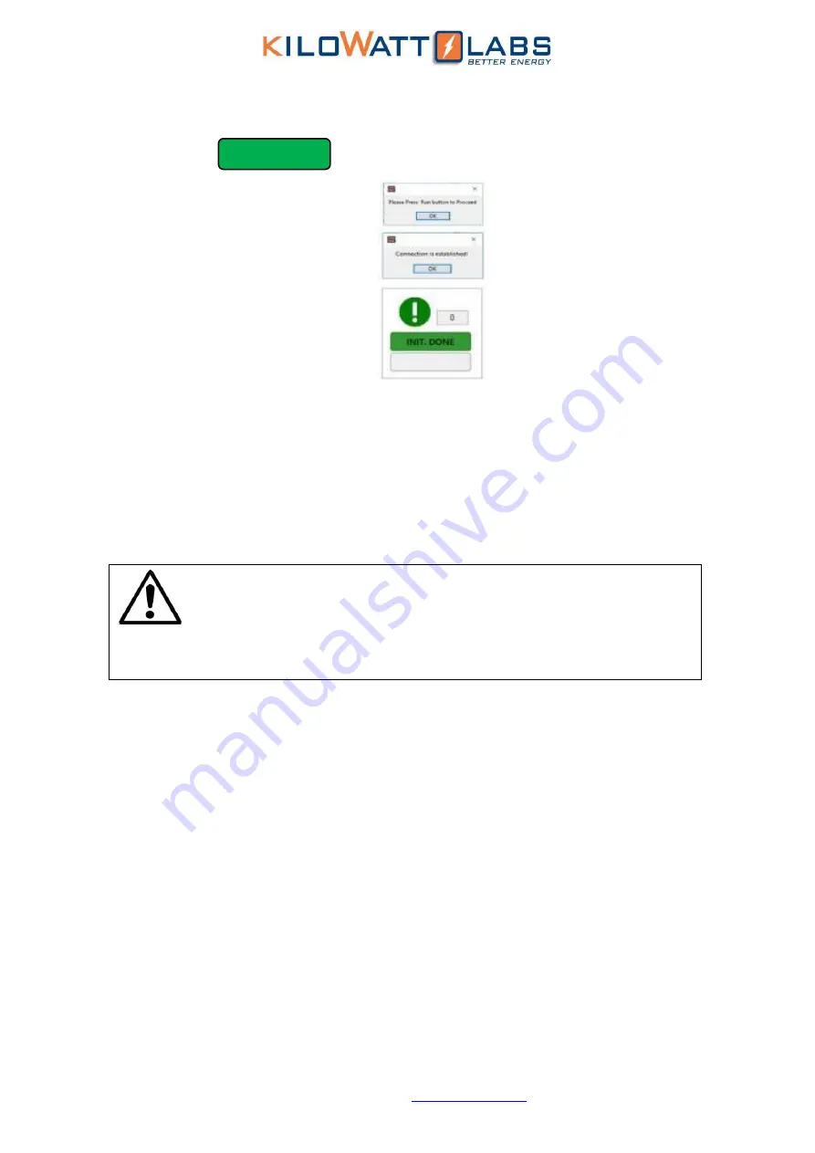
INIT DONE
9.
Follow instructions and press Run on interface. (Auto Pop-up dialogs)
10.
When the connection between the computer and the Module is established successfully,
then the LED will be continually turned on.
11.
For getting measurements, press RUN button.
12.
If there is any problem during connection, check USB cable and ensure the module is
working properly.
13.
While getting measurement, MEASURING LED should blink every 1 second. If blinking has
stopped, it will represent measurement interrupt or technical issues.
14.
While getting measurement, COMM LED on front panel of the Module will blink.
7.
Recovery Procedure
When the Module voltage drops below a certain threshold, the control electronics are turned
OFF.
To
restart the control electronics, follow the steps below:
1.
Use the Unprotected terminal to turn the module
ON
.
2.
A power supply having a voltage range of 44Vdc to 54Vdc and current range of 1A to 10A will
be required.
3.
Connect the
positive
terminal of the power supply to the
positive
terminal of the
Unprotected terminal and
negative
terminal of the power supply to the
negative
terminal of
the Unprotected terminal using the lead provided.
4.
Once the connection is done, turn
ON
the circuit breaker, the module will recharge, and the
control electronics will turn
ON
.
5.
The event may take several minutes depending on the power supply used.
6.
At this stage, remove the power supply and leave the module for normal recharge.
Note!
Please read the Application manual to configure the software thoroughly.
The Application manual is downloaded automatically when you install
SiriusVIEW application.


