SIRIUS CAPACITOR MODULE
User Manual
Model number: 7100-48-B-2C-TM-SD-A-G
Version 1.0; Release Date: July 2019
Author:
Mamoona Khalid
Page 1: ...SIRIUS CAPACITOR MODULE User Manual Model number 7100 48 B 2C TM SD A G Version 1 0 Release Date July 2019 Author Mamoona Khalid...
Page 2: ...change without notice While every attempt has been made to make the Manual accurate and up to date users are cautioned that product improvements may cause the Company to make changes to specifications...
Page 3: ...11 3 Module Installation 14 3 1 Inspection 14 3 2 Safety Gear 15 3 3 Unpacking and Contents Check 15 4 Operation Procedures 16 4 1 Module Configuration 16 4 2 Software Configuration 17 5 Recovery Pro...
Page 4: ...13 Test Procedures 29 13 1 Round Trip Efficiency Test 29 13 3 Test Method for Self Discharge 30 14 FAQs 30...
Page 5: ...rius Modules are designed to provide years of trouble free operation Proper handling is required to avoid damage to the Module In particular the following precautions should be observed Personal Safet...
Page 6: ...Do not touch the terminals with conductors while the Module is charged Serious burns shock or material fusing may occur Protect surrounding electrical components from incidental contact When connecti...
Page 7: ...s are shipped via Sea please follow the instructions given below Carefully remove the Module from the pallets after cutting the packing strip holding the Modules to the shipping pallets Open the carto...
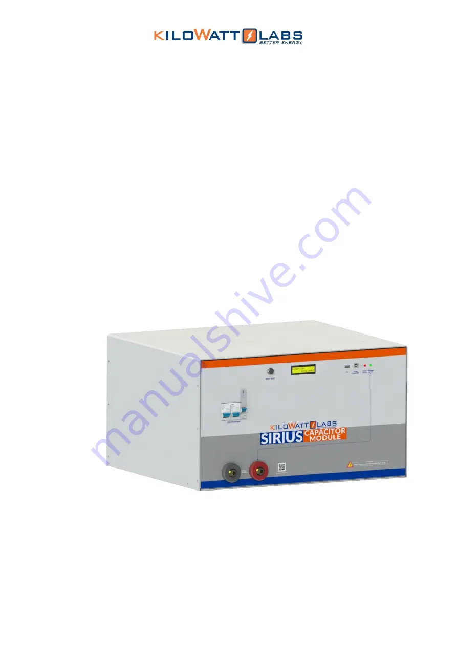
Page 8: ...7100 48 B 2C TM SD A G This manual is subject to change without notice and at the sole discretion of Kilowatt Labs Inc Kilowatt Labs Inc www kilowattlabs com 8 2 2 Product Overview 2 2 1Appearance Th...
Page 9: ...anual Model Number 7100 48 B 2C TM SD A G This manual is subject to change without notice and at the sole discretion of Kilowatt Labs Inc Kilowatt Labs Inc www kilowattlabs com 9 2 2 2Mechanical Drawi...
Page 10: ...or Module User Manual Model Number 7100 48 B 2C TM SD A G This manual is subject to change without notice and at the sole discretion of Kilowatt Labs Inc Kilowatt Labs Inc www kilowattlabs com 10 Side...
Page 11: ...2 2 3Dimension and Weight Width 608mm Length 530mm Height 345mm Weight 125 kg 2 3 Front Panel Description Object Mark Description 1 Circuit Breaker C100A Circuit Breaker 2 2 Bypass Breaker C20A 3 Faul...
Page 12: ...terminal manually after it turns OFF due to any error The additional features of fault reset are as follows a Hold fault reset for 5 seconds to toggle the terminal b Hold fault reset for 3 seconds to...
Page 13: ...om 13 4 LCD Description Once the power is switched ON from the circuit breaker the Module gets power and the LCD shows the following message after 3 seconds under normal operation After 1 second the f...
Page 14: ...or Status Indication Green ON The F12 terminal is active Green OFF The F12 terminal is not active 9 F12 Terminals These are the output terminals of the Module having electronic switch protection that...
Page 15: ...gs and segregation requirements of the end use application Installation must be performed by professional installers only Switch OFF the system and check for hazardous voltages before altering any con...
Page 16: ...abs com 16 4 Operation Procedures 4 1 Module Configuration Follow the steps below to switch ON the Module Step 1 Connecting the Load Connect the F12 terminals of the Module to the load F12 terminals a...
Page 17: ...is OFF 3 Turn OFF the Module by moving the Circuit breaker button to the OFF position 4 2 Software Configuration To configure Sirius VIEW application please follow the steps below 1 Install the Siriu...
Page 18: ...abs Inc Kilowatt Labs Inc www kilowattlabs com 18 6 When the Log In appears enter the default username and password as shown below Default Username admin Default Password 123 7 By clicking on Login th...
Page 19: ...When the connection between PC and Module is established successfully INIT LED will be constantly turned ON 11 For getting measurement press RUN button 12 If there is any problem during connection ch...
Page 20: ...c and current range of 1A to 10A will be required 3 Connect the positive terminal of the power supply to the positive terminal of the F12 terminal and negative terminal of the power supply to the nega...
Page 21: ...overy Maximum Current 10 A Recommended Voltage 44V 54V 6 Connecting the Module in Parallel or in Series The capacity or voltage of the Module can be increased by connecting them in Parallel or Series...
Page 22: ...from the respective common point 6 2 Series Connection of Sirius Modules A maximum of 8 Modules can be connected in Series with a Module Combiner Steps to Connect Modules in Series Refer to the Series...
Page 23: ...the Modules to 100 SOC or same voltage level before connecting them in Series Note Switch ON the bypass Circuit breaker when connecting in Series otherwise it will damage the electronic switch Note Mo...
Page 24: ...www kilowattlabs com 24 Steps to Operate Modules in Series The figure given below shows n number of Modules connected in series 1 Turning ON the Modules 1 First of all turn ON the bypass breakers of...
Page 25: ...unts for 5 seconds and if the current does not drop lower than the cut off and count down has reached to zero the buzzer alarms and the electronic switch will shut down Module Charge Full When the Mod...
Page 26: ...s Warning Messages Description Trouble Shooting Over Current OC OC occurs when the current goes above 296A or when the Module is short circuited In this event the electronic switch will shut down Swit...
Page 27: ...gh Ambient Temperature High Module Temperature 3 Front panel of Sirius Module has LCD and Fault Reset Button The fault reset button acts as a multifunction button for monitoring and configuration By u...
Page 28: ...is 8GB and Module can keep logging 30 days of data without any interruption 4 User can delete and read SD card memory over Sirius VIEW Monitoring Application 5 Sirius Module has one of the best ADC to...
Page 29: ...cy and cost involved in the production line we used constant current load test method for Round trip efficiency characterization Test Equipment DC Charger test system or any other test system which ca...
Page 30: ...ndition The following steps describe the process for measuring self discharge Step 1 Charge the Module to its maximum voltage Record the voltage Vmax Step2 Leave the Module idle for a period of 1 mont...
Page 31: ...happen when connecting different model of Sirius Module parallel series together A Modules can be connected in parallel or in series if they will have Same Voltage Same Capacity It is possible but no...
Page 32: ...r like Voltage Current Temperature Energy Kindly consult with your Reseller for calibration procedure Q What is the reason if the LED isn t working at all A Due to different reasons that may happen su...
Page 33: ...ells inside the Module A Yes but NOT in a movable vibrating position Q What is the difference between the balancing and auto balancing in set Config tab in Sirius VIEW A Balancing Balancing can be act...