


KIESELMANN GmbH | Operating instruction
Commissioning, service and maintenance | 6
6125_APNV_EN
11 / 32
6.2 Service
RECOMMENDATION
Replacement of seals
To achieve optimal maintenance cycles, the following points must be observed!
–
When replacement of seals, all product-contacting seals should be replaced.
–
Only original spare parts may be installed.
Maintenance interval
The maintenance intervals depend on the operating conditions "temperature, temperature-intervals,
medium, cleaning medium, pressure and opening frequency". We recommend replacing the seals 3-
year cycle.The user, however should establish appropriate maintenance intervals according to the
condition of the seals.
Lubricant recommendation
EPDM; HNBR; NBR; FKM; k-flex
- Klüber Paraliq GTE703*
Silicone
- Klüber Sintheso pro AA2*
Thread
- Interflon Food*
*) It is only permitted to use approved lubricants, if the respective fitting is used for the produc-
tion of food or drink. Please observe the relevant safety data sheets of the manufacturers of lub-
ricants.
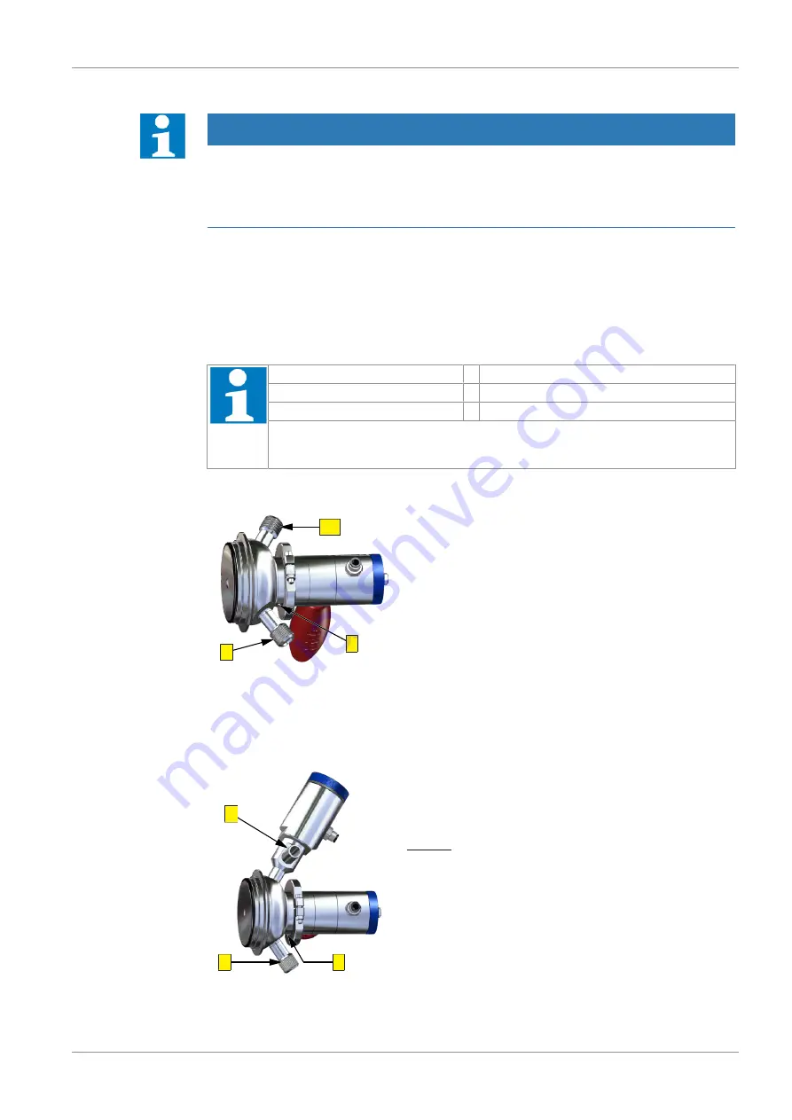
6.3 Cleaning
SP
L
B
The cleaning of the valve occurs in the closed state over con-
nection (B), whereat with concurrent cleaning of the tank or
pipe system the valve can be opened. For valves with rinsing
connection the cleaning occurred via connection (SP).
6.4 Sterilization
The valve can be sterilized with flame, steam or liquid.
Steam - and liquid sterilization
D
L
B
The steam or liquid sterilization proceeds though the outlet
pipe (B) or during tank or pipe cleaning.
For valves with rinsing connection the sterilization occurred
via connection (SP).
Optional the valve can be equipped with a steam valve (DV).
The steam or liquid sterilization occurred via the connection
(D).