


37
Kice Industries, Inc.
FLT-M03-0002
012420
Appendix B Continued
Page 3 of 6
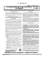
I&M No. V_6584_R19_sec1
©
ASCO Valve, Inc.
50 Hanover Road, Florham Park, New Jersey 07932 www.ascovalve.com
5. Check DIN connector terminal block for electrical
markings. Then make electrical hookup to terminal block
according to markings on it. Snap terminal block into
connector cover and install center screw.
6. Position connector gasket on solenoid and install plug
connector. Torque center screw to 5±1 in
-
lbs [0,6±1,1
Nm].
NOTE:
Alternating current (AC) and direct current (DC)
solenoids are built differently and cannot be converted from one
to the other by changing the coil.
Installation of Solenoid
Solenoids may be assembled as a complete unit. Tightening is
accomplished by means of a hex flange at the base of the solenoid.
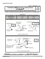
Installation of Panel Mounted Solenoid
(See Figures 1
and 2)
1.
Disassemble solenoid following instruction under
Solenoid
Replacement
then proceed.
2.
Install solenoid base sub
-
assembly through customer panel.
8202H panel mounted solenoids include a retainer to adapt
the solenoid base sub
-
assembly to the customer panel. (See
Figure 2)
3.
Position finger washer on opposite side of panel over solenoid
base sub
-
assembly.
4.
Replace solenoid, nameplate/retainer and red cap.
5.
Make electrical hookup, see
Wiring
section.
Solenoid Temperature
Standard solenoids are designed for continuous duty service.
When the solenoid is energized for a long period, the solenoid
becomes hot and can be touched by hand only for an instant. This
is a safe operating temperature.
MAINTENANCE
WARNING: To prevent the possibility of
death, serious injury or property damage,
turnoff electrical power, depressurize
solenoid operator and/or valve, and vent fluid
to a safe area before servicing.
AVERTISSEMENT: Pour éviter tous danger
de mort, de blessure grave ou de dommage
matériel, avant d’intervenir sur la vanne,
couper le courant, purger la vanne dans une
zone sécurisée.
Cleaning
All solenoid operators and valves should be cleaned
periodically.
The time between cleaning will vary depending
on medium and service conditions. In general, if the voltage to
the solenoid is correct, sluggish valve operation, excessive noise
or leakage will indicate that cleaning is required. Clean strainer
or filter when cleaning the valve.
Preventive Maintenance
•
Keep the medium flowing through the solenoid operator or
valve as free from dirt and foreign material as possible.
•
Periodic exercise of the valve should be considered if
ambient or fluid conditions are such that corrosion, elastomer
degradation, fluid contamination build up, or other conditions
that could impede solenoid valve shifting are possible. The
actual frequency of exercise necessary will depend on specific
operating conditions. A successful operating history is the
best indication of a proper interval between exercise cycles.
•
Depending on the medium and service conditions, periodic
inspection of internal valve parts for damage or excessive
wear is recommended. Thoroughly clean all parts. Replace
any worn or damaged parts.
Causes of Improper Operation
•
Faulty Control Circuit:
Check the electrical system by
energizing the solenoid. A metallic
click
signifies that the
solenoid is operating. Absence of the
click
indicates loss of
power supply. Check for loose or blown fuses, open
-
circuited
or grounded solenoid, broken leadwires or splice connections.
•
Burned-Out Solenoid:
Check for open
-
circuited solenoid.
Replace if necessary. Check supply voltage; it must be the
same as specified on nameplate/retainer and marked on the
solenoid. Check ambient temperature and check that the core
is not jammed.
•
Low Voltage:
Check voltage across the solenoid leads.
Voltage must be at least 85% of rated voltage.
Solenoid Replacement
1.
Disconnect conduit, coil leads, and grounding wire.
NOTE:
Any optional parts attached to the old solenoid must be
reinstalled on the new solenoid. For 3
-
way construction, piping or
tubing must be removed from pipe adapter.
2.
Disassemble solenoids with optional features as follows:
•
Spade or Screw Terminals
Remove terminal connections, grounding screw, grounding
wire, and terminal block (screw terminal type only).
NOTE:
For screw terminals, the socket head screw holding the
terminal block serves as a grounding screw.
•
Junction Box
Remove conduit and socket head screw (use 5/32˝ hex key
wrench) from center of junction box. Disconnect junction
box from solenoid.
•
DIN Plug Connector
Remove center screw from DIN plug connector. Disconnect
DIN plug connector from adapter. Remove socket head
screw (use 5/32˝ hex key wrench), DIN terminal adapter,
and gasket from solenoid.
3. Remove red cap or retainer from top of solenoid base sub
-
assembly. For 3
-
way construction with pipe adapter (Figure
3), remove pipe adapter, nameplate and solenoid. Omit steps 4
and 5.
4. Push down on solenoid. Then using a suitable screwdriver,
insert blade between solenoid and nameplate/retainer. Pry
up slightly and push to remove. NOTE: Series 8202G/H
solenoids have a spacer between the nameplate/retainer and
solenoid.
5. Remove solenoid from solenoid base sub
-
assembly.
6. Reassemble in reverse order of disassembly. Use exploded
views for identification and placement of parts.
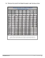
7. Torque pipe adapter to 90 inch
-
pounds maximum [10,2 Nm
maximum]. Then make up piping or tubing to pipe adapter on
solenoid.
Disassembly and Reassembly of Solenoids
1.
Remove solenoid, see
Solenoid Replacement
.
2.
Remove spring washer from solenoid base sub
-
assembly. For
3
-
way construction, remove pipe adapter and plugnut gasket.
3.
Unscrew solenoid base sub
-
assembly from valve body.
4.
Remove internal solenoid parts for cleaning or replacement.
Use exploded views for identification and placement of parts.
5.
If the solenoid is part of a valve, refer to basic valve installation
and maintenance instructions for further disassembly.
6.
Torque solenoid base sub
-
assembly and adapter to 175±25 in
-
lbs [19,8±2,8 Nm].
ORDERING INFORMATION FOR ASCO
SOLENOIDS
When Ordering Solenoids for ASCO Solenoid Operators or
Valves, order the number stamped on the solenoid. Also specify
voltage and frequency.