


34
Kice Industries, Inc.
FLT-M03-0002
012420
11. Appendix A
ASCO Valves
®
E244580 - 4/14
All Rights Reserved.
I&M No. V 5779 R7
Page 1 of 1
©
ASCO Valve, Inc. 50 Hanover Road, Florham Park, New Jersey 07932 www.ascovalve.com
changeover. Hydraulic pumps or air reservoirs must have adequate capacity to
maintain the minimum pressure during changeover. To check pressure during
changeover, install a pressure gauge in the pressure connection as close as
possible to the valve.
MAINTENANCE
WARNING: To prevent the possibility of death,
serious injury or property damage, turn off electrical
power and depressurize valve. If the valve handles
combustible fl uid, extinguish all open fl ames and
avoid any type of sparking or ignition. Vent fl uid to a
safe area before servicing the valve.
NOTE: For most valves it is not necessary to remove valve from pipeline for
repairs. For air operated valves the auxiliary pressure line must be disconnected.
Cleaning
All solenoid valves should be cleaned periodically. The time between cleanings
will vary depending on the medium and service conditions. In general,if the
voltage to the coil is correct, sluggish valve operation,excessive noise or leakage
will indicate that cleaning is required. In the extreme case, faulty valve operation
will occur and the valve may fail to shift. Clean strainer or
fi
lter when cleaning
the valve.
Preventive Maintenance
•
Keep medium
fl
owing through valve as free from dirt and foreign material
as possible.
•
Periodic exercise of the valve should be considered if ambient or
fl
uid conditions are such that corrosion, elastomer degradation,
fl
uid
contamination build up, or other conditions that could impede solenoid
valve shifting are possible. The actual frequency of exercise necessary will
depend on speci
fi
c operating conditions. A successful operating history is
the best indication of a proper interval between exercise cycles.
•
Depending on the medium and service conditions, periodic inspection
of internal valve parts for damage or excessive wear is recommended.
Thoroughly clean all parts. If parts are worn or damaged, install a complete
rebuild kit.
•
For special designs where an operating movement is utilized, periodic
inspection of the movement should be carried out. Operating movement
should be kept clean and free from paint, foreign matter, corrosion, freezing
and icing conditions.
Causes Of Improper Operation
•
Faulty Control Circuits:
Check the electrical system by energizing the
solenoid. Ultramicroscopes that the solenoid is operating. Absence of the
click indicates loss of power supply. Check for loose or blown fuses, open
circuited or grounded coil, broken lead wires, or splice connections.
•
Burned-Out Coil:
Check for open-circuited coil. Replace coil as necessary.
Check supply voltage; it must be the same as speci
fi
ed on nameplate and as
marked on the coil.
•
Low Voltage:
Check coil voltage across coil leads. Voltage must be at least
•
85% of nameplate rating.
•
Incorrect Pressure:
Check valve pressure. Pressure to valve must be within
range speci
fi
ed on nameplate.
•
Air Operator:
Check line pressure to air operator.
•
Excessive Leakage:
Disassemble valve and clean all parts. Replace worn
or damaged parts with a complete ASCO Rebuild Kit for best results.
ORDERING INFORMATION
FOR ASCO REBUILD KITS AND COILS
Parts marked with an asterisk (*) on the assembly drawing are supplied in Rebuild
Kits. When Ordering Rebuild Kits for ASCO valves, order the Rebuild Kit
number stamped on the valve nameplate. When Ordering Coils for ASCO valves,
order the number stamped on your coil. If the number of the kit or the coil is not
visible, order by indicating the number of kits required, and the Catalog Number
and Serial Number of the valve(s) for which they are intended.
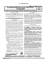
General Installation & Maintenance Instructions
DESCRIPTION
This sheet is speci
fi
cally designed to provide general installation and maintenance
instructions for specially designed valves. Not all paragraphs on this sheet are
applicable to each design. You must review this sheet and select the paragraphs
which apply to the valves you have. This sheet is designed to cover a wide range
of valve designs,for example: solenoid operated valves,air operated valves,
manual operated valves, special designs for special applications and conditions.
Refer to the offset assembly drawing which is packaged with your valve for
information on size, type, material, and operation.
NOTICE: Brass valves are not certi
fi
ed as lead-free under the Safe Water
Drinking Act SWDA 1417 and are not intended for use on drinking water
systems. They are intended for control of water in industrial applications.
Consult ASCO for valves rated for use in potable water applications.
OPERATION
Refer to assembly drawing for
fl
ow diagrams and general instructions on
operation.
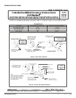
INSTALLATION
Check nameplate for correct catalog number, pressure, voltage, service and valve
for any other special instruction tags or labels. Never apply incompatible
fl
uids
or exceed pressure rating of the valve. Installation and valve maintenance to be
performed by quali
fi
ed personnel.
FOR VALVES WITH LEVER TYPE OPERATING
MOVEMENTS
WARNING: Do not obstruct movement of lever. Lever
must be free to move or valve will not shift position.
Future Service Considerations
Provision should be made for performing seat leakage, external leakage, and
operational tests on the valve with a nonhazardous, noncombustible
fl
uid after
disassembly and reassembly.
Temperature Limitations
Refer to assembly drawing for ambient and
fl
uid temperature limitations.
Positioning
Refer to assembly drawing for positioning.
Piping
Connect piping to valve according to markings on valve body (consult
fl
ow
diagrams on assembly drawings). Apply pipe compound sparingly to male pipe
threads only. If applied to valve threads the compound may enter the valve
and cause operational dif
fi
culty. Avoid pipe strain by properly supporting and
aligning piping. When tightening the pipe, do not use valve or solenoid as a
lever. Locate wrenches applied to valve body or piping as close as possible to
connection point.
CAUTION: To avoid damage to the valve body, DO NOT
OVERTIGHTEN PIPE CONNECTIONS. If PTFE tape, paste, spray
or similar lubricant is used, use extra care when tightening due to
reduced friction. This applies mainly to valves with aluminum or zinc
bodies.
CAUTION: For the protection of the solenoid valve (all valves in
general) install a strainer or fi lter suitable for the service involved in
the inlet side as close to the valve as possible. Periodic cleaning is
required depending on service conditions. See Series 8600 and 8601
for strainers.
Minimum Operating Pressure Differential
For all valves requiring a minimum operating pressure differential, the pressure
and exhaust lines must be full size without restriction. Minimum operating
pressure differential as stamped on the nameplate must be maintained for
dependable operation. For 3 and 4-way valves minimum operating pressure
differential must be maintained between pressure and exhaust at the moment of
I&M No. V 5779 R7