2
Installation
24
Series N8700 User’s Guide
4
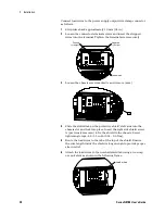
Route the AC wires to the input connector terminals as required.
To connect the wires, loosen the terminal screw, insert the
stripped wire into the terminal, and tighten the screws securely
as indicated in the following figures. Ensure that you have the
green/yellow ground conductor connected to the ground terminal
on the connector. Plug the connector onto the rear panel header
and secure it with the side screws. Screw tightening torque: 10.7
– 13.4 in-lb (1.2 – 1.5 Nm).
or
Plug Type:
PC 6/4-STF-10,16 or PC 6/3-STF-10,16 Phoenix
Wire Size:
AWG 18 to AWG 8
Stripping Length:
12 mm (0.5 in.)
Torque:
10.7 – 13.4 in-lb (1.2 – 1.5 Nm)
5
Route the wires inside the cover to prevent pinching while sliding
the cover towards the rear panel for attachment. Fasten the cover
to the unit using the M3 x 8mm flat head screws provided. Screw
tightening torque: 4.8 in-lb (0.54 Nm). Refer to the following
figure.


