
2
6
Keysight M9018A PXIe 18-Slot Chassis Startup Guide
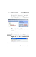
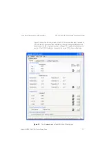
STEP 3: Turn On and Verify Operation of the Chassis System
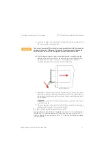
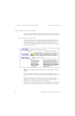
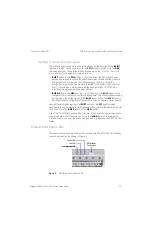
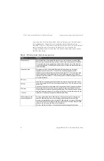
Chassis front panel LEDs
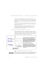
The front panel LEDs, depending on whether they are off, on continuously, or
flashing, provide important information on the status of the chassis, and should
be monitored regularly. Table 5 lists each LED and describes the information it
provides.
The chassis will not intentionally modify its operation because of conditions that
cause one or more LEDs to flash. In other words, the chassis will attempt to
continue normal operation despite flashing LED(s). However, a flashing LED may
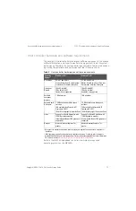
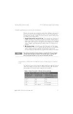
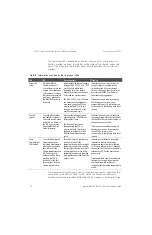
Table 5
Information provided by the front panel LEDs
LED
Off
On continuously
Flashing
Power LED
(blue)
Indicates that the
chassis is turned off.
If you attempt to turn the
chassis on but the Power
LED remains off, this can
indicate several possible
problems — please see
the M9018A User Guide
for details.
Indicates that the four main supply
voltages (3.3V, 5V, 12V, and -12V)
plus 5Vaux are within their
respective limits. The factory
default limits are plus and minus
5% around the nominal values.
The 3.3V, 5V, 12V, and -12V limits
can be individually changed for
each supply using the SFP and
programmatically. The limits, if
changed, are reset to 5% at the
next chassis power cycle.
Indicates that one or more of the four
supply voltages are outside of their
limits, either the 5% factory default
limits or, if changed, the user set limits.
Refer to the M9018A User Guide for
troubleshooting suggestions.
If the power supply condition causing
the flashing to occur is no longer
present, the Power LED will return to on
continuously, i.e. the flashing state is not
latched.
Fan LED
(green)
Typically indicates that
the chassis is turned off.
This could also indicate a
failed LED or a failure of
the LED drive circuitry.
See the M9018A User
Guide for details.
Indicates that all three fans are
operating above 1000 RPM, the
factory default limit.
The fan speed limit can be
changed using the SFP or
programmatically. The limit, if
changed, is reset back to 1000
RPM at the next chassis power
cycle.
Indicates that one or more of the three
fans are operating below the limit, either
the 1000 RPM factory- default limit or, if
changed, the user-set limit.
If the fan speed condition causing the
flashing to occur is no longer present,
the Fan LED will return to on
continuously, i.e. the flashing state is not
latched.
Temp
(Temperature)
LED (amber)
To avoid this amber LED
being interpreted as
indicating a temperature
problem in the on state,
this LED is
off
if the
chassis temperatures are
OK. To allow you to
validate that this LED is
working, the LED is
turned on for the first
three seconds after the
chassis is powered up.
This LED is never on continuously.
It will either be off if the
temperatures reported by the eight
temperature sensors are all below
the limit (see left column), or it will
be flashing if one or more of the
temperature sensors are reporting
a temperature above the limit (see
right column).
Indicates that at least one of the eight
temperature sensors is reporting a
temperature above the limit, either the
70°C factory default limit or, if changed,
the user set limit.The limit, if changed, is
reset back to 70°C at the next chassis
power cycle.
If the temperature condition causing the
flashing to occur is no longer present,
the Temperature LED will turn off,
indicating that the chassis temperatures
are OK.


