


1
4
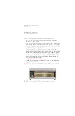
Keysight M9018A PXIe 18-Slot Chassis Startup Guide
STEP 2: Prepare the Hardware and Install the Software
Setting up the chassis on a bench
Setting up the chassis on a bench
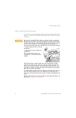
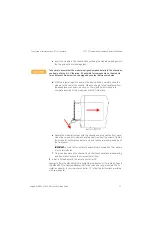
The primary consideration in using the chassis on a bench is ensuring adequate
ventilation for cooling. Cooling air enters through the vent holes on the bottom,
sides, and front of the chassis, and exits through the rear of the chassis. For
bench use, ensure that the feet are installed on the chassis so that air can enter
through the bottom of the chassis. Also ensure that there is at least 50 mm (2
inches) of clearance on the sides, front, and rear of the chassis.
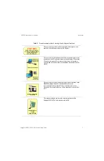
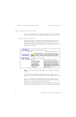
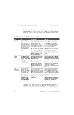
Removing and installing filler panels
The chassis is shipped from the factory with all filler panels installed. For the 18
slots, the filler panels are 20.32 mm (.8 inches) wide; these are referred to as
narrow filler panels
. The expansion slot to the left of slot 1 is three slots wide;
hence, the filler panel for the expansion slot is 60.96 mm (2.4 inches) wide and is
referred to as a
wide filler panel
.
The filler panels are held in place by captive screws (two screws for narrow filler
panels and four screws for wide filler panels). When installing a filler panel, the
captive screws should be tightened securely to ensure the filler panel is
well-grounded to the chassis.
Ensure that filler panels are installed in all empty slots. Missing filler panels will
impact cooling of the chassis and may cause RFI (radio frequency interference)
with other devices.
This guide assumes that chassis preparation, turn-on and verification are
performed on the bench prior to installing the chassis in a rack. If you prefer to
install the chassis in a rack first, please see the M9018A User Guide on the
Software and Product Information CD for rack mounting instructions.
In addition to installing modules and filler panels in chassis slots, air inlet
modules can also be installed in chassis slots. These modules can be placed
adjacent to high power modules for additional cooling. Keysight provides an air
“Appendix A: Chassis and Accessory Model
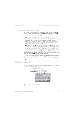
Please do not install modules in the peripheral slots yet. In this step, only slot 1,
the system controller slot, will have a module installed. Deferring the
installation of other modules until later will allow the chassis to be turned on
and verified in its simplest configuration.
To prepare the hardware, either an embedded controller or a PCIe cable
interface module will be installed in slot 1, depending on your configuration.
Both of these installations are described in this step.


