background image

INSTALLATION

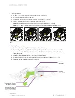
Part 2: Wire the Fixture

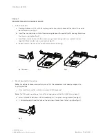
1.  Run power to junction box

a.  Remove the junction box’s outer cover by pressing down on the outer latch and pulling the cover 

toward you.

Note: 

A licensed electrician should perform all the wiring tasks. All electrical connections must 

be made within the junction box.

b.  Run the conduit in (and out, if this is one downlight in a sequence).

Note: 

Maximum of ( 8 ) no. 12 AWG (4 mm2) through branch circuit conductors suitable for  

165 ˚F (75 ˚C) permitted in the box.

c.  Run the building’s power line wires* into the junction box.

2.  Splice the wires

a.  Using the provided connectors, splice the D3’s flying leads into the building’s power. Make sure 

the housing is grounded in accordance with local codes.

b.  Replace the junction box’s outer cover.

3.  Test the wiring

a.  Apply power to the D3. The emitter should immediately come on to 3000 K (warm white).

Note:

 If the emitter comes on red, see Diagnostic Colors, page 18.

b.  Wait several minutes while the D3 tests its installation conditions. Then use the color to determine 

whether installation was successful:

•  If the light stays at 3000 K, installation was successful. Continue to step d.
•  If the light changes color, a problem has been detected.

Note: 

Magenta can indicate success or failure. It indicates success if there are no other 

powered-on Ketra devices within 50 ft (15.2 m); otherwise, it indicates a problem. 
To troubleshoot problems, see 

Diagnostic Colors

, page 18.

c.  After verifying a successful installation, remove power and continue to 

Part Three.

* Ketra lighting products should not be connected to, or directly controlled by, AC mains line voltage dimmers. 

These types of dimmers may also  

be referred to as phase cut, triac, forward-phase, reverse-phase, ELV, or MLV dimmers. Ketra's lighting products should only be controlled via our 
digital control architecture. Ketra does not recommend switching power on/off to Ketra lighting products via relays, contactors, or manual toggle 
switches. When the lighting products are disconnected from power they cannot respond to digital commands from control devices. This could 
confuse end users as the lighting may be in a state that is inconsistent with the control devices. Please refer to our controls products installation 
guides for more information.

D3

 INSTALLATION GUIDE | 11

P/N 3662360 Rev C
© 2019-2020 Ketra, Inc. All rights reserved.

Summary of Contents for CM-D3-HOUSING

Page 1: ...D3 Installation Guide Models HW D3 HOUSING CM D3 HOUSING HW D3 HOUSING X CM D3 HOUSING X HW D3 HOUSING XN CM D3 HOUSING XN...

Page 2: ...e with the instructions may cause harmful interference to radio communications However there is no guarantee that interference will not occur in a particular installation If this equipment does cause...

Page 3: ...nstalling Drywall 12 Part 4a Apply Flangeless Mud In Trim Retainer 12 Part 4b Flangeless Millwork Trim Retainer Installation Wood Stone Ceilings 13 Part 5 Apply Joint Compound 14 Part 6 Apply Trim 14...

Page 4: ...It uses a fully tunable spectrum capable of delivering high quality white saturated and pastel light butterfly bracket butterfly bracket hanger bar slot junction box height adjust tilt lock AC input...

Page 5: ...d Electrical Specifications Wattage Specifications 18 W 120 V 60 Hz 18 W 150 mA 220 277 V 50 60 Hz 18 W 65 mA 82 mA 13 W 120 V 60 Hz 13 W 109 mA 220 277 V 50 60 Hz 13 W 47 mA 60 mA 9 W 120 V 60 Hz 9 W...

Page 6: ...ither nailer bars or butterfly brackets Option 1 Nailer Bars Allow horizontal movement post mounting Ideal with wooden studs or t grid ceilings Option 2 Butterfly Brackets Allows horizontal or vertica...

Page 7: ...3 d Repeat steps a c for the clasps on the other end of the housing fig 1 optional fig 2 fig 4 fig 3 2 Mount downlight in the ceiling Note For optimal radio communication ensure that the radio dome is...

Page 8: ...ing wall wash optic due to possible damage Note If you remove the optic be careful not to touch the exposed silicone dome on the emitter c Unlock the tilt lock by pulling it toward the fixture apertur...

Page 9: ...Restore the original emitter module conditions a Return the emitter chassis to its original position locking the tilt and rotation locks b Wall wash downlight only Reattach the optic Press it flush t...

Page 10: ...does not protrude b Wire tie at least one bracket to the deck using at least one tie 5 Optional If using a square aperture with a flange realign the collar parallel to the wall a Loosen the collar s...

Page 11: ...l If the light stays at 3000 K installation was successful Continue to step d If the light changes color a problem has been detected Note Magenta can indicate success or failure It indicates success i...

Page 12: ...e Circle with 4 in 101 6 mm diameter tolerance 0 25 0 00 3 Align the hole with the D3 s aperture and install the drywall Part 4a Apply Flangeless Mud In Trim Retainer Note Skip this section if you hav...

Page 13: ...rmining the appropriate length needed on the height adjuster break the unwanted portion of the strap while still retaining a barrier for the current screw slot Ensure that the height adjuster is broke...

Page 14: ...inal surface before removing the aperture plug Clean the internal surfaces of the trim retainer with a clean rag and isopropyl alcohol Part 6 Apply Trim Flangeless mud in and flanged downlights have d...

Page 15: ...M SQUARE BEVEL SHEET 860 000067 XX DWG NO PROPRIETARY AND CONFIDENTIAL B 3815 S CAPITAL OF TEXAS HIGHWAY SUITE 100 AUSTIN TEXAS 78704 512 347 1100 DRAWN BY Vendor DATE Vendor PN THIRD ANGLE PROJECTION...

Page 16: ...ation Tilt Rotation Square Trim Only Tilt and Rotation Angle Indication Tilt Rotation Square Trim Only fig 13 fig 14 fig 15 2 Adjusting optic depth a Remove the trim by pulling the trim directly down...

Page 17: ...se the steps shown in Section 3 above to remove the optic and access the power supply c Unhook the emitter cable from the RJ45 jack on the power supply d Pull power supply straight out from the dockin...

Page 18: ...voltage on the power line Ensure that input voltage matches the expected voltage for the D3 s model Magenta Poor wireless connectivity Ensure that the D3 is not in a metal enclosure and that there ar...

Page 19: ...For questions and technical support please contact 844 588 6445 ketrasupport lutron com Ketra and KetraNet are trademarks or registered trademarks of Lutron Ketra LLC in the US and or other countries...

Page 20: ...6231 E Stassney Ln Bldg 13 Suite 400 Austin TX 78744 www ketra com 512 872 4349 P N 3662360 Rev C...

Reviews: