ADDITIONAL OPERATIONS
fig. 18
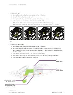
3. Replacing the optic
a. Remove the trim by pulling the trim directly down from the housing.
b. Ensure that the emitter chassis is locked.
c. Grab optic and twist counterclockwise to unlock. Pull toward you to remove.
d. Install replacement optic, twisting clockwise to lock (see
fig. 18
).
Note:
Demonstrate caution when removing wall wash optic due to possible damage.
Note:
If you remove the optic, be careful not to touch the exposed silicone dome on the emitter.
4. Replacing the power supply
a. Remove the trim by pulling the trim directly down from the housing.
b. For all configurations except Wall Wash, tilt the Light Engine to 40˚ and rotate to allow access to the
power supply. For Wall Wash, use the steps shown in
Section 3
(above) to remove the optic and access
the power supply.
c. Unhook the emitter cable from the RJ45 jack on the power supply.
d. Pull power supply straight out from the docking station while depressing docking station latch.
e. Disconnect power supply quick connect (see
fig. 19
).
Primary Optic Replacement
Align to Shoulder Pins and Insert
Twist to Lock
Primary Optic Replacement
Align to Shoulder Pins and Insert
Twist to Lock
Primary Optic Removal
Twist to Unlock (Rotation lock should be set)
Pull to Remove (Optic is not tethered!)
Primary Optic Removal
Twist to Unlock (Rotation lock should be set)
Pull to Remove (Optic is not tethered!)
Tilt locked at 40˚ . Emitter
Module in Full Regress
Disconnect
power supply
Unlocked and rotated so
that Emitter Module tilts
away from Power Supply
Disconnect
emitter module
D3
INSTALLATION GUIDE | 17
P/N 3662360 Rev C
© 2019-2020 Ketra, Inc. All rights reserved.


