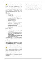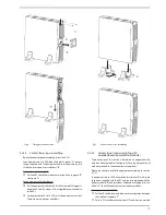
24
4.3.4. Connection of the external batteries
(extended back up time).
•
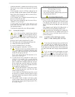
As this is a device with class i protection against electric
shocks, it is essential to install a protective earth con-
ductor (connect earth(
)). Connect the conductor to the ter-
minal, before connecting the power supply to the input power
block.
•
To not respect the stated indications in this section and
the safety instructions 1.2.3 means a high risk of electrical
discharge and even the death.
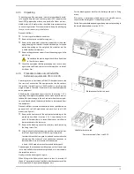
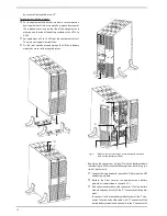
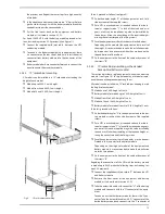
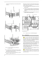
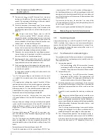
• To connect the batteries with the equipment, follow the de-
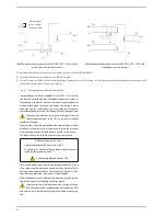
scribed steps in sections 4.2.5.4 and 4.2.5.6.
• All the standard UPSs have batteries in the same enclosure. battery
protection is done by internal fuses and not accessible for the end-
user.
battery modules have internal protections for the batteries too
and they are not accessible for the end-user.
•
iMPoRTAnT FoR SAFETy: in case of installing the bat-
teries by yourself, the accumulators has to be provided
with a two pole circuit breaker protection.
•
before starting the connection between the battery
module/s and the equipment, check that the equipment
switch/es and the one in the battery cabinet are in "off" position.
likewise when batteries are installed by own self, the fuse or
switch has to be turned off.
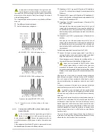
• Connection terminals of external batteries with the equipment
are done with a polarised Anderson connector.
• For battery connection with the equipment, follow the stated
steps in sections 4.2.5.4 and 4.2.5.6, keeping in mind the model.
• in parallel systems (4 to 10 kVA models only), the connection of
the external battery modules with each equipment has to be
treated as single and separate units.
•
Each battery module is independent for each equipment.
it is completely forbidden to connect two equipments to
the same battery module.
4.3.5. Connection of main input earth terminal
(
)
and the earth bonding terminal
(
)
•
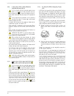
As this is a device with class i protection against electric
shocks, it is essential to install a protective earth con-
ductor (connect earth(
)). Connect the conductor to the ter-
minal, before connecting the power supply to the input power
block.
• Make sure that all the loads connected to the UPS are only con-
nected to the protective earth bonding terminal (
). The fact of
not restricting the earthing of the load or loads and/or the bat-
teries case/s or cabinet/s to this single point will create a return
loops to earth which will affect the quality of the supplied power.
• All terminals identified as earth bonding (
), are joined to-
gether, to the main protective earthing terminal (
) and to
the frame of the device.
4.3.6. Terminals for EPo (Emergency Power
off)
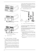
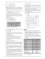
• All UPSs have two terminal to install an external button, for Emer-
gency Power off (EPo). nevertheless, depending on the power
rate of the equipment, it is supplied a four pins connector with the
remote shutdown on-oFF (models from 0,7 to 3 kVA) or a single
connector and individual of two pins (models from 4 to 10 kVA).
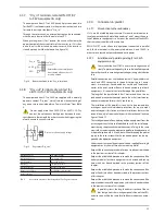
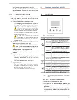
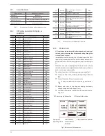
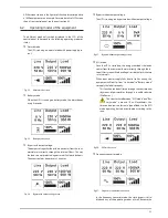
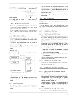
As an illustration mode, figures A and b, it is shown a connector
of two pins.
• by default, the equipment is supplied from factory with the EPo
circuit as open (no). So, the UPS will break the output power
supply, emergency power off, when opening the circuit:
Either by removing the female connector inserted in the
plinth. This connector has a cable bridge to close the circuit
(Fig. A).
Fig. A
Fig. b
or by turning on the external button installed and belonging
to the end-user. The connection in the button has to be in
normally closed because it will open the circuit when turning
it on.
• Through the control panel, it can be selected the reverse func-
tionality, normally closed (nC).
less punctual cases, it is not recommended to use this type of
connection due to the function of the EPo button, because it
would not work in case of any of the two cables that goes from
the button to the UPS were cut (damaged).
on the other hand this failure would be immediately detected
in the normally open EPo type, with the inconvenience of the
sudden break in the power supply to the loads, but with a com-
plete guarantee of the functioning of the emergency power off.
• To restore the normal operating mode of the UPS, the connector with
the cable bridge has to be fitted back in the terminal strip or to de-
activate the EPo button and later on to cancel the EPo status in the
control panel . The equipment will be operative.

