15
4.2.3. Unpacking
• The packaging of the equipment consists of a cardboard enclo-
sure, expanded polystyrene corner pieces (EPS), polyethylene
foam (EPE), polyethylene sleeve and band, all of them are recy-
clable materials; therefore they should be disposed according
to current regulations. we recommend to keep the packaging
in case its use is necessary in the future.
• Proceed as follows:
Cut the strips of cardboard enclosure.
Remove the accessories (cables, supports, ... )
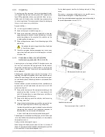
Remove the equipment or battery module from the pack-
aging, keeping in mind that it is needed the help of a second
person depending on the weight of the model or use the
suitable mechanical mediums.
Remove the protection corners from the packaging and the
plastic bag.
Do not leave the plastic bag at the children hand, due
to the risk that it means.
Check the equipment before proceeding and in case dam-
ages where confirmed, contact with the supplier or in lack of
it with our firm.
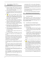
4.2.4. Procedure to take out and install the
batteries in equipments of 4 to 10 kVA
• According to the current trends, all the UPSs have batteries inside
the same rack enclosure of the equipment, but on the contrary
the resultant weight from 4 to 10kVA models is very high (see
weights stated in the table 13 and/or in the own packaging of the
own equipment).
Attending the recommendations stated in the section 1.2.3.2.
regarding the weight manipulation and to make easier the instal-
lation of this power range in the rack cabinet when the manipula-
tions are done by hand, the battery block has to be removed from
the equipment.
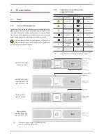
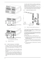
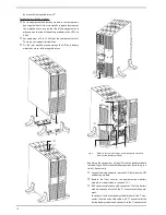
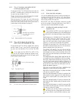
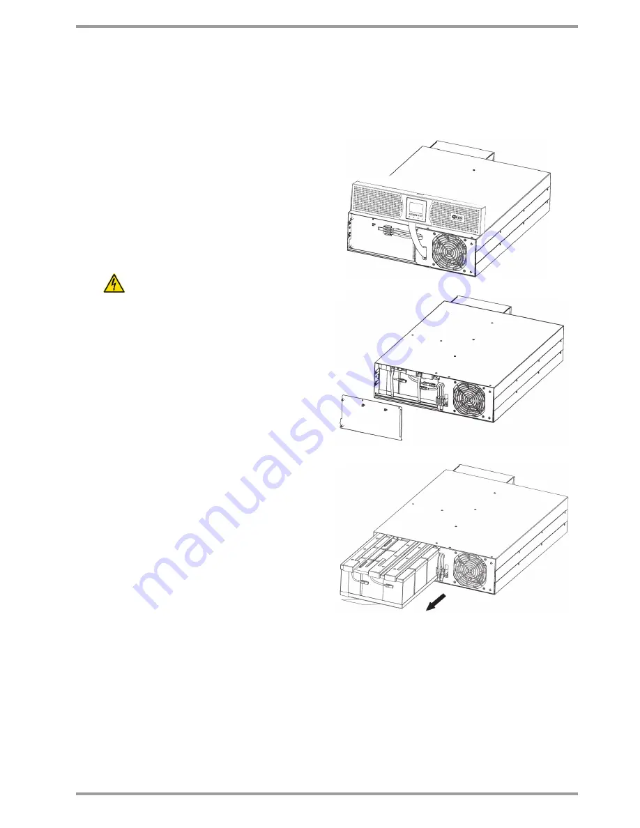
Proceed as follows to remove the battery block or pack, based on
one pack for 4 to 6 kVA models and two packs for 8 and 10 kVA
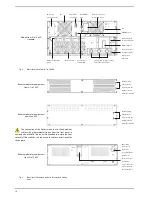
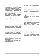
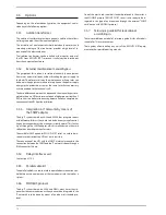
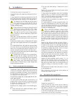
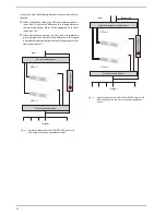
models (see figure 4):
Remove the front cover of the equipment according to the
procedure described in section 4.2.5.2., considering that 8
and 10 kVA models there is a second front cover, which has to
be removed too in the same way.
Remove the blocking cover/s from battery pack, removing
the fixing screws first.
Using the handle that each battery pack has, remove the bat-
tery block by pulling from it till removing it completely.
Consider that each battery pack is wired and connected to the
electronic unit by means of a fast connection connector, so
there could be some resistance to its disconnection.
in 8 and 10 kVA models remove the second battery pack.
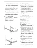
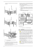
• Depending on the required assembling type, vertical -tower type
- or to be installed in the rack cabinet, proceed as it is described in
the respective sections.
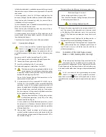
• Finally, insert the battery pack/s again.
when fitting in the battery block, make sure that it is inserted till
the end. The correct electrical joint between the connector of the
battery pack and the equipment depends on it.
• Put the blocking cover back for the battery pack and its fixing
screws.
if this cover is not properly fixed against the metallic chassis,
check that the battery pack is completely inserted.
• Put the front cover back depending on the equipment, according to
the described procedure in section 4.2.5.2..
blocking cover for battery pack
Handle for battery pack
Power rate models from 4 to 6 KVA.


