background image

H O I ® . 

T h e output  v o l t a g e is determined  w i t h  R

2

 and Vref  a s  g i v e n 

a b o v e .  T h e output  v o l t a g e is 0 V if  R

2

 is infinite (open).  S e t 

Vref  w i t h  t h e  v o l t a g e control provided on  t h e panel.  T o fix

 it

 or 

s e t it  e x t e r n a l l y ,  c o n n e c t a  1 0 k  o h m resistor  w h i c h  h a s a 

good  t e m p e r a t u r e  c h a r a c t e r i s t i c  a c r o s s © and ®  a c c o r d i n g 

to  " C o n t r o l  b y  r e s i s t a n c e  ( I ) " .  T h e  v o l t a g e control of  t h e 

panel is  n o w  i n e f f e c t i v e . 

N o t e : 

B e  s u r e to  a d j u s t  t h e output  v o l t a g e at  O U T P U T  O N  m o d e . In 

O U T P U T  O F F or

  V / i

  C H E C K  m o d e ,  t h e r e is

 a

 slight error in 

m e t e r reading. 

C o n t r o l  b y  e x t e r n a l  v o l t a g e 

It

 is  p o s s i b l e  t o output  v o l t a g e  w h i c h is proportional to 

v o l t a g e . 

1)  T u r n off  p o w e r . 

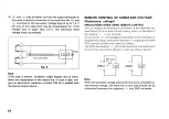
2 )  R e m o v e  t h e short bar  © - ©  a n d  c o n n e c t external voltage 

V

t

  a c r o s s ®  a n d ©  a s  s h o w n  F i g .  9 .  B e  v e r y careful about 

t h e polarity. 

Two-core shield cable 

•Vi 

F i g . 9 

Note: 

T h e external signal voltage  s h o u l d be  0 - 1 0  V .  T h e input im-

p e d a n c e  a c r o s s ® and ® is approximately  1 0 k  o h m s .  U s e a 

t w o - c o r e shield  c a b l e and  c o n n e c t  t h e shield line to  © . 

V

0

 (VI

: Output voltage 

Vi IV]:

 External signal voltage 

Vm,

x

 [VI:

 Maximum rated output voltage. 

REMOTE CONTROL OF CONSTANT CURRENT 
(Resistance, voltage) 

Refer to the  " P R E C A U T I O N S  W H E N  U S I N G  R E M O T E  C O N T R O L " 

under  " R E M O T E  C O N T R O L  O F  C O N S T A N T - V O L T A G E " 

C o n t r o l  b y  r e s i s t a n c e 

C o n t r o l of  c o n s t a n t - c u r r e n t is  p o s s i b l e in proportion  w i t h 

r e s i s t a n c e . 

1)  T u r n off  p o w e r . 

2)  R e m o v e  t h e  s h o r t bar  ® - ® . 

3)  C o n n e c t variable  r e s i s t o r  R 3  ( 1 0 k  o h m s )  a c r o s s ©  a n d ® 

a s  s h o w n  F i g .  1 0 . 

F i g .  1 0 

Two-core 

shield cable 

16 

1 0 

( O s V ^ I O  V ) 

R

Summary of Contents for PD18-20

Page 1: ...P D 8 2 Q 2 0 D P D 8 3 0 3 0 D P D 1 8 2 0 2 0 D P D 1 8 3 0 3 0 D P D 3 5 2 0 2 0 D REGULATED DC POWER SUPPLY INSTRUCTION MANUAL ...

Page 2: ...R PANEL TERMINALS 1 3 REMOTE SENSING 1 3 REMOTE CONTROL OF CONSTANT VOLTAGE RESISTANCE VOLTAGE 14 REMOTE CONTROL OF CONSTANT CURRENT RESISANCE VOLTAGE 16 SERIES PARALLEL CONNECTED OPERATION 17 CONSTANT CURRENT CHARGING DISCHARGING OF BATTERY 2 0 M A I N T E N A N C E A N D A D J U S T M E N T 21 MAINTENANCE 21 ADJUSTMENT 2 3 T R O U B L E S H O O T I N G 25 D I M E N S I O N S 2 6 T h i s manual c...

Page 3: ...nt vary little with temperature The output voltage may be changeable in small steps with a potentiometer turnable as many as ten positions The V l C H E C K switch provided permits to check the preset values of voltage and current even during operation The O U T P U T s w i t c h turns on and off the output Protection is complete from overvoltage overcurrent and excessive temperature rise T h e O ...

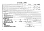
Page 4: ... mV Ripples noises f 10 Hz to 1 MHz rms Note 2 0 5 mV rms Transient response standard value 100 jisec typical Temperature characteristic standard value 100ppm C typical Remote control resistance voltage approx Oto 10 k0 0 to 10 V Current regulation C O With input changes of 1 0 2 mA 3 mA 5 mA 5 mA 5 mA With load changes of 0 to 100 5 mA 5 mA 5 mA 5 mA 5 mA Ripples noises 10 H z t o l MHz rms Note ...

Page 5: ...ed on Function Output switch Turns on and off output preset voltage indicated with meter during off time Voltage current check switch Preset voltage and current indicated with meters during on time Overvoltage protection OVP preset Indicates the over voltage protection level on the voltmeter during on time Remote sensing Via the rear panel senser terminal Series control Master slave control series...

Page 6: ... D including power input connector 411 520 523 483 486 520 523 48 Weight Approx 1 5 kg Approx 20 kg Approx 19 kg Approx 24 kg Approx 23 kg Accessories Instruction manual 1 1 1 1 1 Input power cord 100 V 120 V area 2 or 3 core A C cable 2 m 2 or 3 core A C cable 2 5 m 2 or 3 core AC cable 2 5 m Input power cord 200 V 220 V 240 V area 3 core AC cable 2 m 3 core AC cable 2 5 m Connector retainer 100 ...

Page 7: ...inals and control terminals are connected with jumpers as s h o w n Fig 2 2 The output lines are floating Connect either of the front panel output terminals to G N D normally with short bar 4 ENVIRONMENTAL CONDITIONS 11 Keep the operating temperature range of 0 to 4 0 C If the ambient temperature rises excessively the device s protection s y s t e m works and cuts off power 2 Keep clear the ventil...

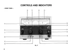
Page 8: ... F R O N T P A N E L CONTROLS AND INDICATORS Fig 3 8 ...

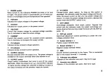
Page 9: ...rically W h e n the output is on the O U T P U T indicator lights and the voltage the voltmeter is reading is output at the output terminals and the ammeter reads the current V l C H E C K Voltage current check switch A s long a s this switch is depressed the voltmeter reads the preset voltage and the am meter the preset current so that you may preset voltage and current T o check the preset volta...

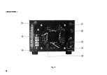
Page 10: ... R E A R P A N E L Fig 4 10 ...

Page 11: ...n Forced air cooled fan Keep it apart from walls more than 3 0 c m C a p C a p of the fuse holder A C input terminals Input terminals of power supply Connect the A C cord provided Fuse holder Input fuse holder of power supply Hole for mounting the retainer of power input connector C a p for concealing optional connector mounting hole 11 ...

Page 12: ...rvoltage protection level is set lower than the preset level of output voltage the power switch will be turned off by overvoltage protection S e e how to set overvoltage proteciton A S A CONSTANT CURRENT POWER SUPPLY 1 C h e c k the rated input voltage then connect the power cord 2 Turn the current adjuster knob CURRENT fully counter clockwise 3 Turn on the power switch The P O W E R red indicator...

Page 13: ...on the O U T P U T switch with no load connected the indicator lights Raising the output voltage gradually check if the power switch turns off at the preset over voltage protection level 4 Set the overvoltage protection level at the maximum reading of the output voltmeter if overvoltage protection is not necessary USE OF REAR PANEL TERMINALS The output and control terminals s h o w n above are equ...

Page 14: ...ce voltage P R E C A U T I O N S W H E N U S I N G R E M O T E C O N T R O L This unit adopts the floating circuit system It has terminals iso lated from the frame and controls output power on the basis of the positive output terminal To control the constant voltage and constant current settings us ing external voltage connect the positive output terminal and G N D terminal on the front panel as f...

Page 15: ...imum rated output voltage Ri kQl External resistance C o n t r o l b y r e s i s t a n c e ID It is possible to output voltage which is inversely proportional to resistance Overshoot does not occur when switching resistance 1 Turn off power 2 Remove the short bar and connect variable resistor R2 across and as shown Fig 8 Use a two core shield cable and connect the shield line to Fig 8 Two core shi...

Page 16: ... off power 2 Remove the short bar and connect external voltage V t across and as s h o w n Fig 9 Be very careful about the polarity Two core shield cable Vi Fig 9 Note The external signal voltage should be 0 1 0 V The input im pedance across and is approximately 10 k ohms Use a two core shield cable and connect the shield line to V 0 VI Output voltage Vi IV External signal voltage Vm x VI Maximum ...

Page 17: ...ms U s e a two core shield cable and connect the shield line to SERIES PARALLEL CONNECTED OPERATION With some units connected in series or in parallel it is possible to control all units with one unit taken as the master and the other as slaves Series connection The output voltage is the sum of the output voltages of the units The output voltage and current of each slave unit are controllable with...

Page 18: ...kQ 36 kfi To obtain R2 replace EJ and E2 with E 3 in the above equation Now master unit controls slave unit and slave unit con trols slave unit Notes 111 These connection conditions are not satisfied on the models below 10 V in rated output For details contact the nearest agent or our distributor 2 Maximum voltage during series operation does not ex ceed rating of the withstand voltage to ground B...

Page 19: ...utput connection diagram s h o w s the negative line grounded The master unit performs constant voltage operation CV and the slave units constant current operation C C For remote sensing during parallel operation make connection from the f S and terminals of the master refer to the section of remote sensing With the rated output voltage is less than 10 V this connec tion is not possible Note For c...

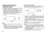
Page 20: ...load resistor R as s h o w n Fig 16 W e assume the bat tery terminal voltage as E and discharging current as I 1 Keeping the V I C H E C K switch depressed set the output voltage at a few volts higher than the battery voltage with the constant voltage control and the discharging current with the constant current control 2 Be sure to connect a load resistor of discharging Direct connection of batte...

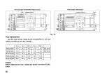
Page 21: ... r e w s on the top and side cases of the unit and pull it up Fig 17 Voltage conversion To convert the device to the line voltage change the power transformer and fuse as noted below It is not necessary to change the fan 21 Power SW F U S E Fig 1 8 MAINTENANCE AND ADJUSTMENT ...

Page 22: ...to the line voltage Voltage selector 100 V 120 V 200 V 220 V 240 V PD8 20 20D 10 A 10 A 4 A 4 A 4 A Rear Panel PD8 30 30D 15 A 15 A 6 A 6 A 6 A Rear Panel PD18 20 20D 15 A 15 A 8 A 8 A 8 A PD18 30 30D 20 A 20 A 10 A 10 A 10 A PD35 20 20D 20 A 20 A 10 A 10 A 10 A Caution Before replacing the f u s e unplug the power cord from the A C outlet 21 Fuse Voltage selector ...

Page 23: ...kwise and the O U T P U T switch turned off adjust V R 8 so that the V meter read 0 V V O U T O F F S E T With the C V control turned fully counterclockwise and the C C control fully clockwise and the O U T P U T switch on adjust V R 1 1 so that the V meter read 0 V Adjustment of V M E T E R GAIN At the rated output adjust V R 7 so that the V meter deflect fully to the end of the scale Adjustment ...

Page 24: ...V I C H E C K s w i t c h o n adjust V R 6 so that the 1 meter read t h e output current A d j u s t m e n t of C E A d j u s t V R 2 0 s o that voltage b e c o m e approximately 4 6 V D C at the b a c k of the emitter resistor and the collector of the series control transistor OPTIONAL ACCESSORIES Rack mount adapter R K 6 0 1 GP IB adapter G P 6 1 0 I O adapter D T 6 1 1 14 ...

Page 25: ...oltage current lamps do not switch 3 Ammeter deflects with output off 4 Oscillating Short bar installed defectively Circuit defective Output diode broken Oscillation by remote sensing Output is excessive 1 Short bar coming off 2 Output voltage current do not fall Short bars and come off Power transistor or control circuit defective Output is not steady 1 Short bar coming off 2 Input voltage wrong ...

Page 26: ...DIMENSIONS Fig 2 0 26 ...

Page 27: ... mm Fig 2 1 PD 8 20 20D 8 30 30D 18 20 20D 18 30 30D 35 20 20D L mm 348 457 420 4 5 7 Lt mm fincluding power input connecterI 32 38 38 38 27 ...

Page 28: ...A product of K E N W O O D C O R P O R A T I O N 17 5 2 chome Shibuya Shibuya ku Tokyo 150 Japan PRINTED IN JAPAN B50 7545 40 u 91 121 110987654321 90 121 11098 ...

Reviews: