


CONSTANT-CURRENT CHARGING/
DISCHARGING OF BATTERY
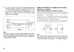
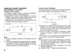
Constant-current charging
It
is possible to c h a r g e a battery or c a p a c i t o r automatically
w i t h a c h a r g i n g current or a final voltage p r e s e t .
1) K e e p i n g t h e V / I C H E C K s w i t c h d e p r e s s e d , s e t t h e final
charging v o l t a g e w i t h t h e c o n s t a n t - v o l t a g e control a n d t h e
c h a r g i n g current w i t h t h e c o n s t a n t - c u r r e n t control.
2) C l o s e s w i t c h
S
l f
a n d c o n s t a n t - c u r r e n t charging s t a r t s a n d
c o n t i n u e s until t h e final voltage is r e a c h e d .
N o t e s :
1 1
! B e s u r e to equalize t h e polarity of t h e s u p p l y p o w e r a n d
battery.
(2) C u r r e n t w o u l d f l o w b a c k into t h e p o w e r s o u r c e if t h e s u p -
ply v o l t a g e
i s
l o w e r t h a n t h e battery v o l t a g e , t h e O U T P U T
s w i t c h is off, or p o w e r s u p p l y is turned off. In this c a s e
r e c o n n e c t diode
D
t
in t h e f o r w a r d direction.
Constant-current discharging
C o n n e c t load resistor R a s s h o w n F i g . 1 6 . W e a s s u m e t h e bat-
tery terminal v o l t a g e a s E a n d discharging current a s I.
1) K e e p i n g t h e V / I C H E C K s w i t c h d e p r e s s e d , s e t t h e output
voltage at a f e w v o l t s higher t h a n t h e battery voltage w i t h
t h e c o n s t a n t - v o l t a g e control a n d t h e discharging current
w i t h t h e c o n s t a n t - c u r r e n t control.
2) B e s u r e to c o n n e c t a load resistor of d i s c h a r g i n g . (Direct
c o n n e c t i o n of battery or c a p a c i t o r m a y c a u s e d a m a g e to
this unit) .
3) C l o s e s w i t c h S
2
, a n d c o n s t a n t - c u r r e n t discharging s t a r t s
and c o n t i n u e s until t h e final voltage is r e a c h e d .
N o t e s :
(1) U s e s w i t c h
S
2
to turn o n a n d off d i s c h a r g i n g . (If t h e O U T -
P U T s w i t c h or p o w e r s w i t c h is off, current f l o w s in this
unit through t h e protecting diode c o n n e c t e d in parallel
w i t h t h e o u t p u t terminals.)
(2) B e c a r e f u l about t h e p o w e r c o n s u m p t i o n of t h e load
resistor of d i s c h a r g i n g .
(3) C o n n e c t t h e bloc'
i
diode to protect t h e battery.
20
Output switch
P o w e r .
supply
F i g . 1 5
Batter
y
Capacito
r
Power
supply
R =
- y -
IQ] P = P x
R [WJ
F i g . 1 6
Batter
y
Capacito
r


