Output current
Maximum rated current
External resistance
N o t e :
R V
3
m u s t be 1 0 k o h m s or l e s s ( R
3
^ 1 0 kQ). U s e a t w o - c o r e
shield c a b l e a n d c o n n e c t t h e shield line to © .
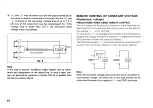
Control by external voltage
It is p o s s i b l e to control c o n s t a n t current in proportion to
v o l t a g e .
1) T u r n off p o w e r .
2) R e m o v e t h e short bar ® - ( 9 ) and c o n n e c t external voltage
V
2
a c r o s s (9) a n d © a s s h o w n F i g . 1 1 . B e v e r y careful
about t h e polarity.
F i g . 1 1
Two-core shield cable
j
m a x
l
0
[AJ: Output current
\Q == X V
2
[A]
Lax
[A]: Maximum rated current
1
^ V
2
[V]: External signal voltage
N o t e :
T h e e x t e r n a l signal v o l t a g e s h o u l d be 0 - 1 0 V . T h e input im-
p e d a n c e a c r o s s (9) a n d (Q) is approximately 1 0 k o h m s . U s e
a t w o - c o r e shield c a b l e a n d c o n n e c t t h e shield line to © .
SERIES/PARALLEL CONNECTED OPERATION
W i t h s o m e units c o n n e c t e d in s e r i e s or in parallel, it is p o s s i b l e
to control all units w i t h one unit t a k e n a s t h e m a s t e r and t h e
other a s s l a v e s .
Series connection
T h e output v o l t a g e is t h e s u m of t h e output v o l t a g e s of t h e
units. T h e output voltage a n d current of e a c h s l a v e unit are
controllable w i t h t h e c o n s t a n t - v o l t a g e a n d c o n s t a n t - c u r r e n t
controls of t h e m a s t e r unit.
1
1
T u r n off p o w e r .
2) R e m o v e t h e short bar ( 3 ) - ® of e a c h s l a v e unit.
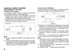
3) C o n n e c t external resistor R a s s h o w n F i g . 1 2 .
4 ) G r o u n d t h e G N D terminal either of t h e m a s t e r unit
if
t h e
positive line is g r o u n d e d or of t h e last s l a v e unit
if
t h e
n e g a t i v e line is g r o u n d e d . ( T h e output c o n n e c i t o n diagram
s h o w s t h e n e g a t i v e line grounded.)
17
O u t p u t current l
0
= ^ x R
3
[A]
l
0
[A]:
I ™
[A]:
R
3
M i :

